
Page 550 - 02. Subyek Computer Aided Design - Beginner’s Guide to SOLIDWORKS 2019- Level 1 by Alejandro Reyes
P. 550
Assembly Modeling
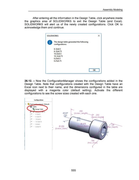
After entering all the information in the Design Table, click anywhere inside
the graphics area of SOLIDWORKS to exit the Design Table (and Excel).
SOLIDWORKS will alert us of the newly created configurations. Click OK to
acknowledge them and continue.
SOLIDWORKS X
The design table generated the following
configurations:
6-32xQ.S
6-32xQ.75
10.32xQ.5
10-32xQ.75
0.25x0.5
0.25x0.75
I OK I
26.12. - Now the ConfigurationManager shows the configurations added in the
Design Table. Note that configurations created with the Design Table have an
Excel icon next to their name, and the dimensions configured in the table are
displayed with a magenta color (default setting). Activate the different
configurations to see the screw sizes created with each one.
Conftgurations
llJc: Design Table
.500
1
(Screw _Lengih)
1=.... 6-32x0.5
t-x - 6-32x0.75
t=x - 10.32x0.5
(Dl)
t-x - 10-32x0.75
t=x - 0.25x0.5 (/).375
~ - 0.25x0.75 </>.250 Head_Diam)
0
(Screw _Diam)
.188
(Hex_Dri
555