Page 554 - 02. Subyek Computer Aided Design - Beginner’s Guide to SOLIDWORKS 2019- Level 1 by Alejandro Reyes
P. 554

Assembly Modeling


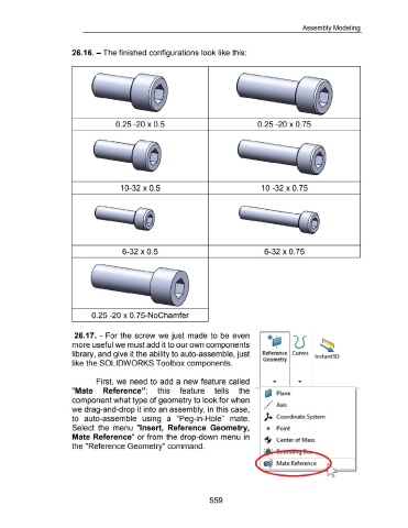
                                                      26.16.- The finished configurations look like this:


                                                                                      0.25 -20 X 0.5                                                                                          0.25 -20 X 0.75


                                                                                          10-32 X 0.5                                                                                            10 -32 X 0.75


                                                                                           6-32 X 0.5                                                                                              6-32 X 0.75


                                                                    0.25 -20 x 0.75-NoChamfer


                                                        26.17.  - For the  screw we just made to  be  even


                                                      more useful we must add it to our own components


                                                      library, and give it the ability to auto-assemble, just                                                                                     Reference  Curves                      lnstant3D

                                                                                                                                                                                                  Geometry
                                                      like the SOLIDWORKS Toolbox components.


                                                                        First,  we need to  add  a  new feature called


                                                      "Mate                  Reference";                             this            feature                   tells            the                         Plane


                                                      component what type of geometry to look for when


                                                      we drag-and-drop it into an assembly, in this case,


                                                      to  auto-assemble  using  a  "Peg-in-Hole"  mate.                                                                                            ). Coordinate System


                                                      Select  the  menu  "Insert,  Reference  Geometry,                                                                                              o  Point


                                                      Mate Reference" or from the drop-down menu  in                                                                                               -$- Center of Mass


                                                      the "Reference Geometry" command.


                                                                                                                                                           559
   549   550   551   552   553   554   555   556   557   558   559