
Page 593 - 02. Subyek Computer Aided Design - Beginner’s Guide to SOLIDWORKS 2019- Level 1 by Alejandro Reyes
P. 593
Assembly Modeling
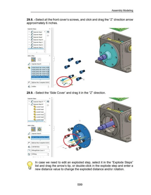
29.8. -Select all the front cover's screws, and click and drag the "Z" direction arrow
approximately 6 inches.
--
~
Explode Steps .... - - ~,.
~ ~ Explode Step7
~ ~ Explode StepS
~ ~ Explode Step9
~ ~ Explode Step10
~ ~ Explode Step11
~ ~ Explode Step12
~ ~ Explode Step13
Add a Step
rt} I Explode Step14
~ socket head cap screw_ai-8@
socket head cap screw_ai-10~
socket head cap screw_ai"6@
socket head cap screw_ai-9@
socket head cap screw_ai-5@
socket head cap screw_al-7@
X
0
~ I Z@Gear Box Complete.SLDASI
I ~
~ I O.OOOin
29.9. -Select the 'Side Cover' and drag it in the "Z" direction.
Explode Steps ,.. "'
~ ~ Explode Step13* "'
... rt} Explode Step14*
~ socket head
~ socket head
~ socket head
~ socket head
~ socket head
~ socket head y
1--.....o.-0--- ~
Add a Step
rtJ I Explode Step15
Side Cover-1 @Gear Box Com
X
0
~ I Z@Gear Box Complete.SLDA51
~ 15.94788703in I :
1~+1 1 XYRing@Side Cover-1
1:
~ I O.OOdeg
In case we need to edit an exploded step, select it in the "Explode Steps"
list and drag the arrow's tip, or double-click in the explode step and enter a
new distance value to change the exploded distance and/or rotation.
599