
Page 211 - Bio Engineering Approaches to Cancer Diagnosis and Treatment
P. 211
210 CHAPTER 8 Ultrasound applications in cancer therapy
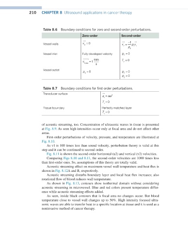
Table 8.6 Boundary conditions for zero and second-order perturbations.
Zero-order Second-order
Vessel walls v = 0 v = − 1 ρ v
0
v →=0 2 ρ 11
0
v →=−1ρ ρ v → 0
2 0 1 1
Vessel inlet Fully developed velocity p = 0
2
p =0 mm
2
2
T =0 v 0,ave = 1 s T = 0
2
v0,ave→=1 mms
Vessel outlet
=0
p
p =0 p = 0 p = 0
0 2
0
2
p =0 p = 0
2
2
Table 8.7 Boundary conditions for first-order perturbations.
Transducer surface
a →=aw 2 a = aω 2
1
1
T = 0
T =0 1
1
Tissue boundary Perfectly matched layer
T =0 T = 0
1
1
of acoustic streaming, too. Concentration of ultrasonic waves in tissue is presented
at Fig. 8.9. As seen high intensities occur only at focal area and do not affect other
areas.
First-order perturbations of velocity, pressure, and temperature are illustrated at
Fig. 8.10.
As v1 is 100 times less than sound velocity, perturbation theory is valid at this
step and it can be continued to second order.
Fig. 8.11 is shown the second-order horizontal (u2) and vertical (v2) velocities.
Comparing Figs 8.10 and 8.11, the second-order velocities are 1000 times less
than first-order ones. So, assumptions of this theory are totally valid.
Acoustic streaming effect on maximum vessel wall temperature and heat flux is
shown in Fig. 8.12A and B, respectively.
Acoustic streaming disturbs boundary layer and local heat flux increases; also
rotational flow of blood reduces wall temperature.
As shown in Fig. 8.13, contours show isothermal domain without considering
acoustic streaming in microvessel. Blue and red colors present temperature differ-
ence while acoustic streaming effects added.
As seen, inside black contours that is focal area no changes occur. But blood
temperature close to vessel wall changes up to 50%. High intensity focused ultra-
sonic waves are able to transfer heat to a specific location at tissue and it is used as a
noninvasive method of cancer therapy.