
Page 331 - Biodegradable Polyesters
P. 331
12.5 The MFC Concept for Preparation of Polymer–Polymer Composites 309
12.5
The MFC Concept for Preparation of Polymer–Polymer Composites with Superior
Mechanical Properties
A fibrillar polymer–polymer composite consists of an isotropic matrix polymer
with fibrils of a second polymer dispersed within it. The idea was developed by
Fakirov et al. [40] with the knowledge that drawing of polymers with good molec-
ular orientation enhances their mechanical properties. Depending on the fibril
diameters, such composites are referred to as microfibrillar composites (MFCs)or
nanofibrillar composites (NFCs). For simplicity, MFCs are discussed because the
manufacturing process is essentially the same. One method of creating MFCs is
to produce a blend of the two selected polymers in the form of a continuous wire.
The blend partners must be thermodynamically immiscible such that one polymer
acts as a matrix and the second polymer exists as dispersed particles within this
matrix. The wire is then drawn by applying tension to invoke necking. The mate-
rial elongates from the necks until the entire wire has necked and drawn. During
this process, the dispersed phase is transformed from spherical particles to high
aspect-ratio fibrils. The transformation involves stretching and coalescence of the
dispersed particles. Coalescence is key to the creation of very high aspect-ratio
fibrils [41]. The process is shown schematically in Figure 12.5.
Some of the advantages of MFCs as outlined by Fakirov and Evstatiev
[42] include the following: reinforcement of polymer by polymer, enhanced
mechanical properties versus the same blend with both polymers in an isotropic
Cross-sectional view of wire (parallel
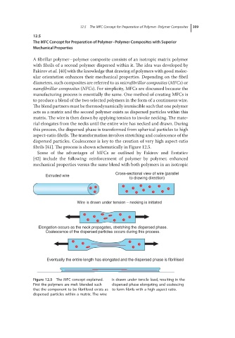
Extruded wire
to drawing direction)
Wire is drawn under tension – necking is initiated
Elongation occurs as the neck propagates, stretching the dispersed phase.
Coalescence of the dispersed particles occurs during this process.
Eventually the entire length has elongated and the dispersed phase is fibrillised
Figure 12.5 The MFC concept explained. is drawn under tensile load, resulting in the
First the polymers are melt blended such dispersed phase elongating and coalescing
that the component to be fibrillized exists as to form fibrils with a high aspect ratio.
dispersed particles within a matrix. The wire