
Page 332 - Biodegradable Polyesters
P. 332
310 12 Biodegradable Polyesters Polymer–Polymer Composites
state, no mineral additives, reduction in weight compared with other composites
(e.g., glass fiber composites), easy processing, no need for compatibilizers, and
recyclability [42]. Furthermore, as the reinforcement is created in situ,the prob-
lem of agglomeration which commonly occurs in micro- and nanocomposites is
circumvented [43].
12.5.1
Preparation of Polymer–Polymer Composites from PLLA/PGA Blends
PLLA/poly(glycolic acid)(PGA) blends were produced via melt blending using a
twin-screw extruder. The extruded blends were collected as a continuous wire for
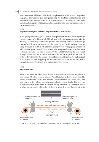
drawing. The next step in the MFC process was drawing. This was done using a
custom-built drawing rig, consisting of a tunnel heated by 16 radiator elements
along its length. It had two sets of rollers, each powered by high-precision motors
with variable speed control. The undrawn wire was passed through the first set of
rollers and then into the heated tunnel. At the end of the tunnel, the wire passed
through the second set of rollers and was collected on a spool, Figure 12.6. In
order to draw the wire, the second set of rollers was set to rotate at a higher speed
than the first set – thus applying the necessary tension to initiate necking and to
elongate the wire. The drawn wire was collected on a spool.
12.5.2
MFC Film Molding
After PLLA/PGA wire had been drawn it was analyzed via scanning electron
microscopy (SEM) to confirm whether PGA fibrils had in fact been created. The
results revealed that PGA fibrils were successfully created (as shown later). The
next step was to evaluate the reinforcing effect of these fibrils. The best way
to determine the upper limit of the reinforcing capability of the fibrils was to
produce specimens in which the fibrils were aligned in one direction, that is,
Rollers, at rotational Rollers, at rotational
speed S 1 speed S 2 > S 1
Necking of filament
Heating elements
Spool of undrawn Spool of drawn
PLLA/PGA PLLA/PGA
Figure 12.6 Schematic diagram of the drawing rig used for drawing PLLA/PGA wire.