
Page 333 - Biodegradable Polyesters
P. 333
12.6 Properties of PLA/PGA Polymer–Polymer Nanofibrillar Composites 311
0.2
0 T comp.molding = 185 °C
−0.2
Heat flow (W g −1 ) −0.4 x
−0.6
−0.8
PGA
m
−1 T = 221 °C
PLLA
T = 151 °C
m
−1.2
0 50 100 150 200 250 300
Temperature (°C)
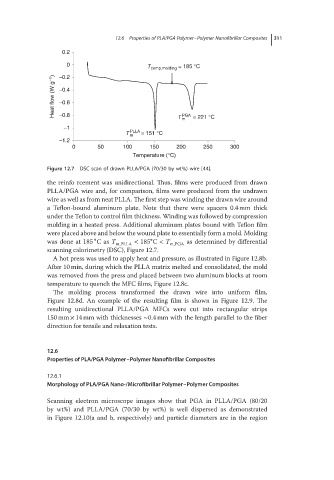
Figure 12.7 DSC scan of drawn PLLA/PGA (70/30 by wt%) wire [44].
the reinfo rcement was unidirectional. Thus, films were produced from drawn
PLLA/PGA wire and, for comparison, films were produced from the undrawn
wire as well as from neat PLLA. The first step was winding the drawn wire around
a Teflon-bound aluminum plate. Note that there were spacers 0.4 mm thick
under the Teflon to control film thickness. Winding was followed by compression
molding in a heated press. Additional aluminum plates bound with Teflon film
were placed above and below the wound plate to essentially form a mold. Molding
∘ ∘
was done at 185 Cas T m,PLLA < 185 C < T m,PGA as determined by differential
scanning calorimetry (DSC), Figure 12.7.
A hot press was used to apply heat and pressure, as illustrated in Figure 12.8b.
After 10 min, during which the PLLA matrix melted and consolidated, the mold
was removed from the press and placed between two aluminum blocks at room
temperature to quench the MFC films, Figure 12.8c.
The molding process transformed the drawn wire into uniform film,
Figure 12.8d. An example of the resulting film is shown in Figure 12.9. The
resulting unidirectional PLLA/PGA MFCs were cut into rectangular strips
150 mm × 14 mm with thicknesses ∼0.4 mm with the length parallel to the fiber
direction for tensile and relaxation tests.
12.6
Properties of PLA/PGA Polymer–Polymer Nanofibrillar Composites
12.6.1
Morphology of PLA/PGA Nano-/Microfibrillar Polymer–Polymer Composites
Scanning electron microscope images show that PGA in PLLA/PGA (80/20
by wt%) and PLLA/PGA (70/30 by wt%) is well dispersed as demonstrated
in Figure 12.10(a and b, respectively) and particle diameters are in the region