
Page 155 - Biomedical Engineering and Design Handbook Volume 1, Fundamentals
P. 155
132 BIOMECHANICS OF THE HUMAN BODY
A limitation of active target systems is that on-board electronics must be strapped to the subject
with leads to each of the diodes. These wires, combined with the subject being tethered to the
cameras can interfere with certain movements. Tetherless systems (i.e., telemetered systems) are
available; however, wires to each diode are still necessary.
In contrast, passive tracking targets merely reflect projected light and do not actively communi-
cate their position in space. It is therefore important that the tracking targets reflect more light than
surrounding objects. To promote this, tracking targets are covered with a highly reflective material,
most often in the form of retroreflective tape; however, reflective ink or paint can also be used. In
addition, a ring of stroboscopic LEDs mounted around the camera lens housing is used to illuminate
the tracking targets (see right panel of Fig. 6.4).
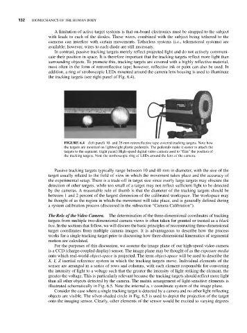
FIGURE 6.4 (left panel) 10- and 25-mm retroreflective tape covered tracking targets. Note how
the targets are mounted on lightweight plastic pedestals. The pedestals make it easier to attach the
targets to the segment. (right panel) High-speed digital video camera used to “film” the position of
the tracking targets. Note the stroboscopic ring of LEDs around the lens of the camera.
Passive tracking targets typically range between 10 and 40 mm in diameter, with the size of the
target usually related to the field of view in which the movement takes place and the accuracy of
the experimental setup. There is a trade-off in target size since overly large targets may obscure the
detection of other targets, while too small of a target may not reflect sufficient light to be detected
by the cameras. A reasonable rule of thumb is that the diameter of the tracking targets should be
between 1 and 2 percent of the largest dimension of the calibrated workspace. The workspace may
be thought of as the region in which the movement will take place, and is generally defined during
a system calibration process (discussed in the subsection “Camera Calibration”).
TheRole of the Video Camera. The determination of the three-dimensional coordinates of tracking
targets from multiple two-dimensional camera views is often taken for granted or treated as a black
box. In the sections that follow, we will discuss the basic principles of reconstructing three-dimensional
target coordinates from multiple camera images. It is advantageous to describe how the process
works for a single tracking target prior to discussing how three-dimensional kinematics of segmental
motion are calculated.
For the purposes of this discussion, we assume the image plane of our high-speed video camera
is a CCD (charge-coupled display) sensor. The image plane may be thought of as the exposure media
onto which real-world object-space is projected. The term object-space will be used to describe the
X, Y, Z inertial reference system in which the tracking targets move. Individual elements of the
sensor are arranged in a series of rows and columns, with each element responsible for converting
the intensity of light to a voltage such that the greater the intensity of light striking the element, the
greater the voltage. This is particularly relevant because the tracking targets should reflect more light
than all other objects detected by the camera. The matrix arrangement of light-sensitive elements is
illustrated schematically in Fig. 6.5. Note the internal u, v coordinate system of the image plane.
Consider the case where a single tracking target is detected by a camera and no other light-reflecting
objects are visible. The silver-shaded circle in Fig. 6.5 is used to depict the projection of the target
onto the imaging sensor. Clearly, other elements of the sensor would be excited to varying degrees