
Page 157 - Biomedical Engineering and Design Handbook Volume 1, Fundamentals
P. 157
134 BIOMECHANICS OF THE HUMAN BODY
Substituting λ into Eq. (6.3) and (6.4), and introducing the following:
β =α /α (6.6)
ij ij 34
leads to two convenient expressions relating the coordinates of the center of the target in the image
plane and the location of the target in the object-space.
u = β 11 X + β 12 Y + β 13 Z + β 14 − uβ 31 X uβ 32 Y − uβ 33 Z (6.7)
−
v = β 21 X + β 22 Y + β 23 Z + β 24 − vβ 31 X − vβ 32 Y − vβ 33 Z (6.8)
Note that the u, v coordinates of the target are known. Therefore, if the X, Y, Z coordinates of the target
are also known, we are left with 11 unknowns (i.e., transformation parameters) in two equations. The
unknown betas (i.e., β ij ) can be determined if the X, Y,
Z coordinates of at least six control points are detected
by the camera. That is, each control point provides two
equations that can be used to solve for the 11 unknown
betas. The term control point is used to make clear that
the X, Y, Z coordinates for these targets are known, having
been accurately measured relative to the origin of the
object-space. The control points are used solely for the
purposes of calibrating the cameras and are removed
from the field of view once the cameras have been
calibrated. The distribution of the n ≥ 6 control points
must not be colinear and the control points should
encompass the volume within which the movement will
take place. This volume is often referred to as the work-
space. One method of defining the workspace is to hang
four strings with a number control points attached to
each string, as shown in Fig. 6.6.
The direct linear transformation (DLT) proposed by
Abdel-Aziz and Karara (1971) is perhaps the most well-
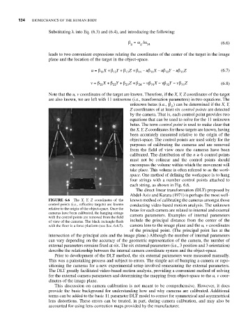
FIGURE 6.6 The X, Y, Z coordinates of the known method of calibrating the cameras amongst those
control points (i.e., reflective targets) are known conducting video-based motion analysis. The unknown
relative to the origin of the object-space. Once the betas for each camera are related to internal and external
cameras have been calibrated, the hanging strings
with the control points are removed from the field camera parameters. Examples of internal parameters
of view of the cameras. The black rectangle flush include the principal distance from the center of the
with the floor is a force platform (see Sec. 6.4.5). camera lens to the image plane and the u, v coordinates
of the principal point. (The principal point lies at the
intersection of the principal axis and the image plane.) Although the number of internal parameters
can vary depending on the accuracy of the geometric representation of the camera, the number of
external parameters remains fixed at six. The six external parameters (i.e., 3 position and 3 orientation)
describe the relationship between the internal camera coordinate system and the object-space.
Prior to development of the DLT method, the six external parameters were measured manually.
This was a painstaking process and subject to errors. The simple act of bumping a camera or repo-
sitioning the cameras for a new experimental setup involved remeasuring the external parameters.
The DLT greatly facilitated video-based motion analysis, providing a convenient method of solving
for the external camera parameters and determining the mapping from object-space to the u, v coor-
dinates of the image plane.
This discussion on camera calibration is not meant to be comprehensive. However, it does
provide the basic background for understanding how and why cameras are calibrated. Additional
terms can be added to the basic 11 parameter DLT model to correct for symmetrical and asymmetrical
lens distortions. These errors can be treated, in part, during camera calibration, and may also be
accounted for using lens correction maps provided by the manufacturer.