
Page 156 - Biomedical Engineering and Design Handbook Volume 1, Fundamentals
P. 156
BIOMECHANICS OF HUMAN MOVEMENT 133
depending on the ambient lighting, but have been turned
off for the sake of this example. Figure 6.5 is also help-
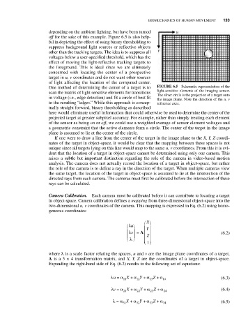
ful in depicting the effect of using binary thresholding to
suppress background light sources or reflective objects
other than the tracking targets. The idea is to suppress all
voltages below a user-specified threshold, which has the
effect of moving the light-reflective tracking targets to
the foreground. This is ideal since we are ultimately
concerned with locating the center of a prospective
target in u, v coordinates and do not want other sources
of light affecting the location of the computed center.
One method of determining the center of a target is to FIGURE 6.5 Schematic representation of the
light-sensitive elements of the imaging sensor.
scan the matrix of light sensitive elements for transitions The silver circle is the projection of a target onto
in voltage (i.e., edge detection) and fit a circle of best fit the image plane. Note the direction of the u, v
to the resulting “edges.” While this approach is concep- reference axes.
tually straight forward, binary thresholding as described
here would eliminate useful information that could otherwise be used to determine the center of the
projected target at greater subpixel accuracy. For example, rather than simply treating each element
of the sensor as being on or off, we could use a weighted average of sensor element voltages and
a geometric constraint that the active elements form a circle. The center of the target in the image
plane is assumed to lie at the center of the circle.
If one were to draw a line from the center of the target in the image plane to the X, Y, Z coordi-
nates of the target in object-space, it would be clear that the mapping between these spaces is not
unique since all targets lying on this line would map to the same u, v coordinates. From this it is evi-
dent that the location of a target in object-space cannot be determined using only one camera. This
raises a subtle but important distinction regarding the role of the camera in video-based motion
analysis. The camera does not actually record the location of a target in object-space, but rather
the role of the camera is to define a ray in the direction of the target. When multiple cameras view
the same target, the location of the target in object-space is assumed to lie at the intersection of the
directed rays from each camera. The cameras must first be calibrated before the intersection of these
rays can be calculated.
Camera Calibration. Each camera must be calibrated before it can contribute to locating a target
in object-space. Camera calibration defines a mapping from three-dimensional object-space into the
two-dimensional u, v coordinates of the camera. This mapping is expressed in Eq. (6.2) using homo-
geneous coordinates:
⎛ X ⎞
⎛ λu⎞ ⎜ ⎟
Y
⎜ λv = A ⎜ ⎟
⎟
⎜ ⎟ ⎜ Z ⎟ (6.2)
⎝ λ ⎠ ⎜ ⎟
⎝ ⎠
1
where λ is a scale factor relating the spaces, u and v are the image plane coordinates of a target,
A is a 3 × 4 transformation matrix, and X, Y, Z are the coordinates of a target in object-space.
Expanding the right-hand side of Eq. (6.2) results in the following set of equations:
λu = α X + α Y + α Z + α 14 (6.3)
11
12
13
λv = α X + α Y + α Z + α 24 (6.4)
23
21
22
λ = α X + α Y + α Z + α 34 (6.5)
32
31
33