
Page 164 - Biomedical Engineering and Design Handbook Volume 1, Fundamentals
P. 164
BIOMECHANICS OF HUMAN MOVEMENT 141
ACS shank . An antero-posterior (AP) axis lies perpendicular to the frontal plane of the shank, with a
medio-lateral (ML) axis formed by the cross product of the longitudinal and AP axes. Unit vectors
Y and Z originating at the COM of the shank are used to define the direction of the AP and ML
s
s
axes, respectively. The X , Y and Z unit vectors are orthonormal by way of construction and form
s
s
s
the basis of the ACS shank (see right panel, Fig. 6.10).
A similar approach can be used to construct ACSs for other segments in the kinematic chain given
suitable placement of anatomical targets (Cappozzo et al., 1995). Figure 6.11 illustrates ACSs for the
shank and thigh without specifying the exact details of how the ACS thigh was constructed.
Although anatomical targets are used to construct the ACSs, and it is motion of the ACSs that is
of interest, it is not practical to track motion of the anatomical targets because they are prone to being
knocked off, and in many cases pose line of sight problems. The medial malleolus and femoral
condyle targets are especially prone to these problems. From a data collection perspective, it is
easier to track targets attached to a segment that have been positioned for optimal viewing by the
cameras than it is to track targets over anatomical sites. If we define a relationship between the tracking
targets and the ACS, we can estimate how the bones are moving by tracking motion of targets on the
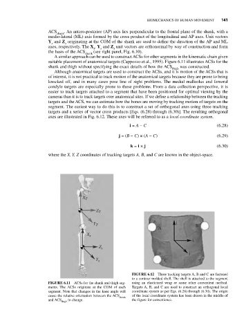
segment. The easiest way to do this is to construct a set of orthogonal axes using three tracking
targets and a series of vector cross products [Eqs. (6.28) through (6.30)]. The resulting orthogonal
axes are illustrated in Fig. 6.12. These axes will be referred to as a local coordinate system.
i = A − C (6.28)
j = (B − C) × (A − C) (6.29)
k = i × j (6.30)
where the X, Y, Z coordinates of tracking targets A, B, and C are known in the object-space.
X T
Z T
Y T i B
A
X s
k
Z s
j
Y s C
FIGURE 6.12 Three tracking targets A, B and C are fastened
to a contour molded shell. The shell is attached to the segment
FIGURE 6.11 ACSs for the shank and thigh seg- using an elasticized wrap or some other convenient method.
ments. The ACSs originate at the COM of each Targets A, B, and C are used to construct an orthogonal local
segment. Note that changes in the knee angle will coordinate system as per Eqs. (6.28) through (6.30). The origin
cause the relative orientation between the ACS of the local coordinate system has been drawn in the middle of
shank
and ACS to change. the figure for convenience.
thigh