
Page 342 - Biomedical Engineering and Design Handbook Volume 2, Applications
P. 342
320 DIAGNOSTIC EQUIPMENT DESIGN
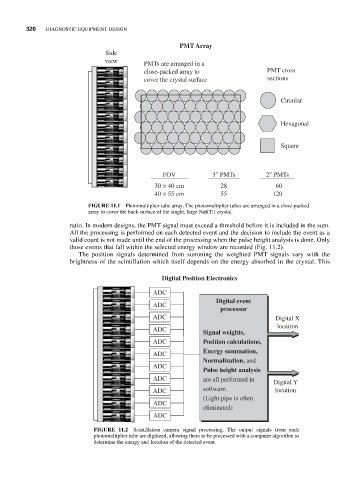
PMT Array
Side
view PMTs are arranged in a
close-packed array to PMT cross
cover the crystal surface sections
Circular
Hexagonal
Square
FOV 3" PMTs 2" PMTs
30 × 40 cm 28 60
40 × 55 cm 55 120
FIGURE 11.1 Photomultiplier tube array. The photomultiplier tubes are arranged in a close-packed
array to cover the back surface of the single, large NaI(Tl) crystal.
ratio. In modern designs, the PMT signal must exceed a threshold before it is included in the sum.
All the processing is performed on each detected event and the decision to include the event as a
valid count is not made until the end of the processing when the pulse height analysis is done. Only
those events that fall within the selected energy window are recorded (Fig. 11.2).
The position signals determined from summing the weighted PMT signals vary with the
brightness of the scintillation which itself depends on the energy absorbed in the crystal. This
Digital Position Electronics
ADC
Digital event
ADC
processor
ADC Digital X
location
ADC
Signal weights,
ADC Position calculations,
Energy summation,
ADC
Normalization, and
ADC
Pulse height analysis
ADC are all performed in Digital Y
ADC software. location
(Light pipe is often
ADC
eliminated)
ADC
FIGURE 11.2 Scintillation camera signal processing. The output signals from each
photomultiplier tube are digitized, allowing them to be processed with a computer algorithm to
determine the energy and location of the detected event.