
Page 346 - Biomedical Engineering and Design Handbook Volume 2, Applications
P. 346
324 DIAGNOSTIC EQUIPMENT DESIGN
Spatial Linearity Correction
New location
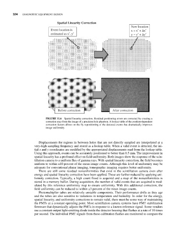
Event location is x = x′ + Δx′
estimated as x′, y′ y = y′ + Δy′
Before correction After correction
FIGURE 11.6 Spatial linearity correction. Residual positioning errors are corrected by creating a
correction map from the image of a precision hole phantom. A lookup table of the position-dependent
correction factors allows on the fly repositioning of the detected events that dramatically improves
image uniformity.
Displacements for regions in between holes that are not directly sampled are interpolated at a
very-high sampling frequency and stored as a lookup table. When a valid event is detected, the ini-
tial x and y coordinates are modified by the appropriated displacements read from the lookup table.
Using this approach, events can be accurately positioned to better than 0.5 mm. The improvement in
spatial linearity has a profound effect on field uniformity. Both images show the response of the scin-
tillation camera to a uniform flux of gamma rays. With spatial linearity correction, the field becomes
uniform to within ±10 percent of the mean image counts. Although this level of uniformity may be
adequate for conventional planar imaging, tomographic imaging requires better uniformity.
There are still some residual nonuniformities that exist in the scintillation camera even after
energy and spatial linearity correction have been applied. These are further reduced by applying uni-
formity correction. Typically, a high count flood is acquired and a map of the nonuniformities is
stored in a memory buffer. During acquisition, the number of valid events that are acquired is mod-
ulated by this reference uniformity map to ensure uniformity. With this additional correction, the
field uniformity can be reduced to within ±3 percent of the mean image counts.
Photomultiplier tubes are relatively unstable components. Their performance drifts as they age
and the tubes are also sensitive to variations in temperature and humidity. In order for the energy,
spatial linearity, and uniformity corrections to remain valid, there must be some way of maintaining
the PMTs at a constant operating point. Most scintillation camera systems have PMT stabilization
firmware that dynamically adjusts the PMTs in response to a known reference signal. Some vendors
use a constant output light-emitting diode inside the detector housing that flashes at a rate of 10 times
per second. The individual PMT signals from these calibration flashes are monitored to compare the