
Page 350 - Biomedical Engineering and Design Handbook Volume 2, Applications
P. 350
328 DIAGNOSTIC EQUIPMENT DESIGN
but the easiest to implement is the subtraction method where information is simultaneously acquired
into a second energy window centered below the photopeak in Compton scatter region of the energy
spectrum. After establishing an appropriate normalization factor, the counts from the scatter window
are subtracted from the photopeak window and the corrected projections are then used in the recon-
struction algorithm.
One other correction that has been implemented with SPECT studies is the compensation for
14
spatial resolution. As discussed in the section on scintillation cameras, the spatial resolution depends
on the source to collimator distance. As a result this correction cannot be made with the analytic recon-
struction methods (i.e., filtered backprojection) but has been implemented with iterative reconstruction
algorithms.
11.3.1 SPECT Image Reconstruction
The details of SPECT image reconstruction are beyond the scope of this article, but the interested
reader can see the details in the cited literature. 15,16 Because SPECT image sets are relatively small
compared to other medical imaging modalities, the computational and display requirements can be met
by personal computers. However, the integration of SPECT studies with CT and MRI put increased
demands on memory and storage.
11.3.2 SPECT System Performance
4
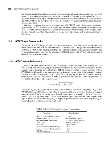
Typical performance specifications for SPECT imaging systems are summarized in Table 11.3. As
with conventional planar imaging, the scintillation cameras and the associated collimation are the
primary factors affecting the performance. SPECT spatial resolution is nearly isotropic with a
FWHM of 8 to 10 mm for brain imaging where the detectors can get close to the radioactive source.
The spatial resolution degrades to 12 to 18 mm for body imaging because the detectors cannot be
positioned as close. The components of SPECT spatial resolution and their relative importance can
be identified from the equation shown below:
2
R SPECT = R col + R 2 filter + R 2 int
As before, R int and R col represent the intrinsic and collimator resolution components. R filter is the
FWHM of the smoothing kernel required to yield an acceptable reconstruction. The intrinsic spatial
resolution is the least important factor in this calculation since it is usually a factor of 2 or more
smaller than the other components. The trade-off between spatial resolution and count sensitivity is
explicit in this equation. Decreasing R col to improve spatial resolution will often require R filter to
become larger to compensate for increased noise.
TABLE 11.3 SPECT System Performance (Typical Values)
Parameter Specification
Number of scintillation cameras 1, 2, or 3
Count sensitivity per camera 90 cps/MBq per detector
(High-resolution collimator) (200 cpm/μCi per detector)
Matrix size 64 × 64; 128 × 128
Pixel size 6 mm; 3 mm
Spatial resolution (brain studies) 8 mm
Spatial resolution (heart studies) 12 mm
SPECT uniformity 15%