
Page 344 - Biomedical Engineering and Design Handbook Volume 2, Applications
P. 344
322 DIAGNOSTIC EQUIPMENT DESIGN
ray originating in the patient is absorbed in the NaI(Tl) crystal. The light from the scintillation is
sampled by the PMT array which determines both the x and y coordinates of the event and its energy.
If the energy signal falls within the window of the pulse height analyzer, the x and y coordinates are
used to increment the appropriate pixel. This process is repeated for every detected event.
In order to form images with a scintillation camera, a collimator must be mounted in front of the NaI(Tl)
crystal. The collimator is the image-forming aperture of the camera system, and it is necessary for the imag-
2
ing process. The collimator projects the gamma ray pattern originating in the patient onto the NaI(Tl) crys-
tal by selectively absorbing diverging gamma rays. The collimator is a close-packed array of holes with
lead walls. Most often the holes have a parallel orientation, but collimators with a fan or cone beam geom-
etry are available. Pinhole collimators are also used for some clinical imaging and are the mainstay of small
animal systems. Gamma rays whose trajectory takes them through a hole get to interact with the NaI(Tl),
while all the others are absorbed. The design of collimators depends on the gamma ray energy and the ever-
present trade-off between count sensitivity and spatial resolution. Collimators used for imaging 99m Tc
typically have holes that are 1 to 1.5 mm across and are 20 to 40 mm thick.
Although collimators are necessary for the formation of images, they are the limiting factor in both
the count sensitivity and spatial resolution of the scintillation camera. Less than 1 in 5000 gamma rays
that hit the front surface of the collimator get through to the crystal. To improve the count sensitivity,
the collimator hole size could be increased and the hole length shortened. Unfortunately, these
changes degrade the spatial resolution. The spatial resolution of the collimator is constrained by the
geometry of the holes and is typically in the range of 6 to 8 mm at 10 cm when used with 99m Tc. This
is the dominant factor in determining the overall system resolution since the intrinsic spatial resolution
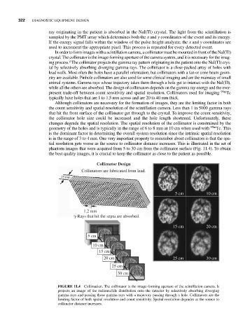
is in the range of 3 to 4 mm. One very important property to remember about collimators is that the spa-
tial resolution gets worse as the source to collimator distance increases. This is illustrated in the set of
phantom images that were acquired from 5 to 30 cm from the collimator surface (Fig. 11.4). To obtain
the best quality images, it is crucial to keep the collimator as close to the patient as possible.
Collimator Design
Collimators are fabricated from lead.
25 mm
5 cm 10 cm
1.2 mm
γ-Rays that hit the septa are absorbed.
15 cm 20 cm
5 cm
10 cm
15 cm
20 cm 25 cm 30 cm
25 cm
30 cm
FIGURE 11.4 Collimation. The collimator is the image-forming aperture of the scintillation camera. It
projects an image of the radionuclide distribution onto the detector by selectively absorbing diverging
gamma rays and passing those gamma rays with a trajectory passing through a hole. Collimators are the
limiting factor of both spatial resolution and count sensitivity. Spatial resolution degrades as the source to
collimator distance increases.