
Page 183 - Boiler_Operators_Handbook,_Second_Edition
P. 183
168 Boiler Operator’s Handbook
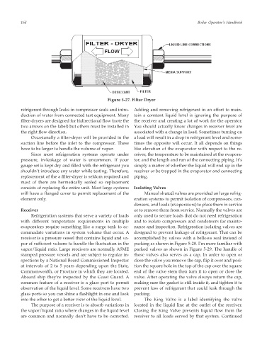
Figure 5-27. Filter Dryer
refrigerant through leaks in compressor seals and intro- Adding and removing refrigerant in an effort to main-
duction of water from connected test equipment. Many tain a constant liquid level is ignoring the purpose of
filter-dryers are designed for bidirectional flow (note the the receiver and creating a lot of work for the operator.
two arrows on the label) but others must be installed in You should actually know changes in receiver level are
the right flow direction. associated with a change in load. Sometimes turning on
Occasionally a filter-dryer will be provided in the a load will result in a drop in refrigerant level and some-
suction line before the inlet to the compressor. These times the opposite will occur. It all depends on things
have to be larger to handle the volume of vapor. like elevation of the evaporator with respect to the re-
Since most refrigeration systems operate under ceiver, the temperature to be maintained at the evapora-
pressure, in-leakage of water is uncommon. If your tor, and the length and run of the connecting piping. It’s
gauge set is kept dry and filled with the refrigerant you simply a matter of whether the liquid will end up in the
shouldn’t introduce any water while testing. Therefore, receiver or be trapped in the evaporator and connecting
replacement of the a filter-dryer is seldom required and piping.
most of them are hermetically sealed so replacement
consists of replacing the entire unit. Most large systems Isolating Valves
will have a flanged cover to permit replacement of the Manual shutoff valves are provided on large refrig-
element only. eration systems to permit isolation of compressors, con-
densers, and loads (evaporators) to place them in service
Receiver or to remove them from service. Normally the valves are
Refrigeration systems that serve a variety of loads only used to secure loads that do not need refrigeration
with different temperature requirements in multiple and to isolate compressors and condensers for mainte-
evaporators require something like a surge tank to ac- nance and inspection. Refrigeration isolating valves are
commodate variations in system volume that occur. A designed to prevent leakage of refrigerant. That can be
receiver is a pressure vessel that contains liquid and va- accomplished by valves with a bellows seal instead of
por of sufficient volume to handle the fluctuation in the packing as shown in Figure 5-28. I’m more familiar with
vapor/liquid ratio. Large receivers are normally ASME packed valves as shown in Figure 5-29. The handle of
stamped pressure vessels and are subject to regular in- those valves also serves as a cap. In order to open or
spections by a National Board Commissioned Inspector close the valve you remove the cap, flip it over and posi-
at intervals of 2 to 5 years depending upon the State, tion the square hole in the top of the cap over the square
Commonwealth, or Province in which they are located. end of the valve stem then turn it to open or close the
Aboard ship they’re inspected by the Coast Guard. A valve. After operating the valve always return the cap,
common feature of a receiver is a glass port to permit making sure the gasket is still inside it, and tighten it to
observation of the liquid level. Some receivers have two prevent loss of refrigerant that could leak through the
glass ports so you can shine a flashlight in one and look packing.
into the other to get a better view of the liquid level. The King Valve is a label identifying the valve
The purpose of a receiver is to absorb variations in located in the liquid line at the outlet of the receiver.
the vapor/liquid ratio where changes in the liquid level Closing the King Valve prevents liquid flow from the
are common and normally don’t have to be corrected. receiver to all loads served by that system. Continued