
Page 179 - Boiler_Operators_Handbook,_Second_Edition
P. 179
164 Boiler Operator’s Handbook
If there isn’t enough liquid entering the evaporator to Adjustable orifice
ensure most of its internal surface is exposed to boiling An adjustable orifice produces a pressure drop
liquid, overall heat transfer will be reduced. by restricting flow (Figure 5-21). Unlike a capillary the
In some of the graphics that follow you will note pressure drop is generated right at the valve. As the
the formation of bubbles within the stream of liquid leav- name implies an adjustable orifice is manually adjusted.
ing the throttling device. This always occurs because the It requires an operator adjust it while observing evapo-
temperature of the liquid at the outlet of the condenser rator pressure and outlet temperature. They should only
is always higher than the saturation temperature main- be used when the load on the evaporator is very stable
tained in the evaporator. Also, the ambient temperature and consistent.
is usually higher than the evaporator temperature so the
liquid refrigerant cannot be cooled by air around the liq- Automatic Expansion Valve
uid piping. A very small portion of the liquid vaporizes An automatic expansion valve simply maintains
absorbing heat from the rest of the liquid to lower its a constant pressure in the evaporator, (Figure 5-22). In
temperature to the saturation temperature in the evapo- addition to the one shown these can be manufactured
rator. with an external sensing line so the pressure that’s con-
trolled is at a different location than the valve outlet. An
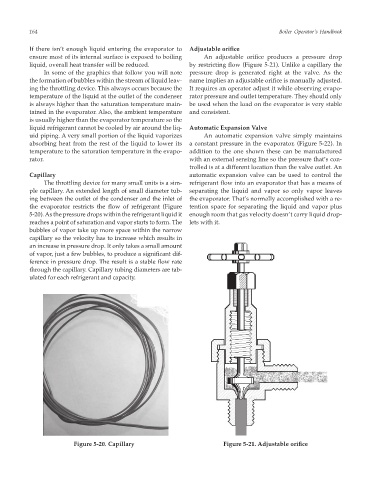
Capillary automatic expansion valve can be used to control the
The throttling device for many small units is a sim- refrigerant flow into an evaporator that has a means of
ple capillary. An extended length of small diameter tub- separating the liquid and vapor so only vapor leaves
ing between the outlet of the condenser and the inlet of the evaporator. That’s normally accomplished with a re-
the evaporator restricts the flow of refrigerant (Figure tention space for separating the liquid and vapor plus
5-20). As the pressure drops within the refrigerant liquid it enough room that gas velocity doesn’t carry liquid drop-
reaches a point of saturation and vapor starts to form. The lets with it.
bubbles of vapor take up more space within the narrow
capillary so the velocity has to increase which results in
an increase in pressure drop. It only takes a small amount
of vapor, just a few bubbles, to produce a significant dif-
ference in pressure drop. The result is a stable flow rate
through the capillary. Capillary tubing diameters are tab-
ulated for each refrigerant and capacity.
Figure 5-20. Capillary Figure 5-21. Adjustable orifice