
Page 180 - Boiler_Operators_Handbook,_Second_Edition
P. 180
Refrigeration & AC 165
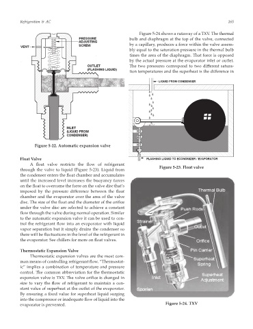
Figure 5-24 shows a cutaway of a TXV. The thermal
bulb and diaphragm at the top of the valve, connected
by a capillary, produces a force within the valve assem-
bly equal to the saturation pressure in the thermal bulb
times the area of the diaphragm. That force is opposed
by the actual pressure at the evaporator inlet or outlet.
The two pressures correspond to two different satura-
tion temperatures and the superheat is the difference in
Figure 5-22. Automatic expansion valve
Float Valve
A float valve restricts the flow of refrigerant
Figure 5-23. Float valve
through the valve to liquid (Figure 5-23). Liquid from
the condenser enters the float chamber and accumulates
until the increased level increases the buoyancy forces
on the float to overcome the force on the valve disc that’s
imposed by the pressure difference between the float
chamber and the evaporator over the area of the valve
disc. The size of the float and the diameter of the orifice
under the valve disc are selected to achieve a constant
flow through the valve during normal operation. Similar
to the automatic expansion valve it can be used to con-
trol the refrigerant flow into an evaporator with liquid
vapor separation but it simply drains the condenser so
there will be fluctuations in the level of the refrigerant in
the evaporator. See chillers for more on float valves.
Thermostatic Expansion Valve
Thermostatic expansion valves are the most com-
mon means of controlling refrigerant flow. “Thermostat-
ic” implies a combination of temperature and pressure
control. The common abbreviation for the thermostatic
expansion valve is TXV. The valve orifice is changed in
size to vary the flow of refrigerant to maintain a con-
stant value of superheat at the outlet of the evaporator.
By ensuring a fixed value for superheat liquid surging
into the compressor or inadequate flow of liquid into the
evaporator is prevented. Figure 5-24. TXV