
Page 414 - Boiler_Operators_Handbook,_Second_Edition
P. 414
Controls 399
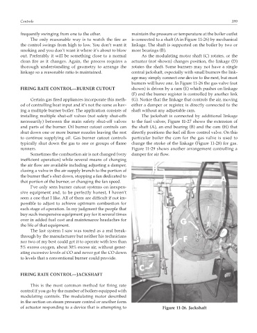
frequently swinging from one to the other. maintain the pressure or temperature at the boiler outlet
The only reasonable way is to watch the fire as is connected to a shaft (A in Figure 11-26) by mechanical
the control swings from high to low. You don’t want it linkage. The shaft is supported on the boiler by two or
smoking and you don’t want it where it’s about to blow more bearings (B).
out. Preferably it will be something close to a normal As the modulating motor shaft (C) rotates, or the
clean fire as it changes. Again, the process requires a actuator (not shown) changes position, the linkage (D)
thorough understanding of geometry to arrange the rotates the shaft. Some burners may not have a single
linkage so a reasonable ratio is maintained. central jackshaft, especially with small burners the link-
age may simply connect one device to the next, but most
burners will have one. In Figure 11-26 the gas valve (not
FIRING RATE CONTROL—BURNER CUTOUT shown) is driven by a cam (E) which pushes on linkage
(F) and the burner register is controlled by another link
Certain gas fired appliances incorporate this meth- (G). Notice that the linkage that controls the air, moving
od of controlling heat input and it’s not the same as hav- either a damper or register, is directly connected to the
ing a multiple burner boiler. The application consists of shaft without any adjustable cam.
installing multiple shut-off valves (not safety shut-offs The jackshaft is connected by additional linkage
necessarily) between the main safety shut-off valves to the fuel valves, Figure 11-27 shows the extension of
and parts of the burner. Oil burner cutout controls can the shaft (A), an end bearing (B) and the cam (H) that
shut down one or more burner nozzles leaving the rest directly positions the fuel oil flow control valve. On this
to continue supplying oil. Gas burner cutout controls particular boiler the cam for the gas valve is used to
typically shut down the gas to one or groups of flame change the stroke of the linkage (Figure 11-28) for gas.
runners. Figure 11-29 shows another arrangement controlling a
Sometimes the combustion air is not changed (very damper for air flow.
inefficient operation) while several means of changing
the air flow are available including adjusting a damper,
closing a valve in the air supply branch to the portion of
the burner that’s shut down, stopping a fan dedicated to
that portion of the burner, or changing the fan speed.
I’ve only seen burner cutout systems on inexpen-
sive equipment and, to be perfectly honest, I haven’t
seen a one that I like. All of them are difficult if not im-
possible to adjust to achieve optimum combustion for
each stage of operation. In my judgment the people that
buy such inexpensive equipment pay for it several times
over in added fuel cost and maintenance headaches for
the life of that equipment.
The last system I saw was touted as a real break-
through by the manufacturer but neither his technicians
nor two of my best could get it to operate with less than
5% excess oxygen, about 30% excess air, without gener-
ating excessive levels of CO and never got the CO down
to levels that a conventional burner could provide.
FIRING RATE CONTROL—JACKSHAFT
This is the most common method for firing rate
control if you go by the number of boilers equipped with
modulating controls. The modulating motor described
in the section on steam pressure control or another form
of actuator responding to a device that is attempting to Figure 11-26. Jackshaft