
Page 419 - Boiler_Operators_Handbook,_Second_Edition
P. 419
404 Boiler Operator’s Handbook
arm and connecting rod flipping.
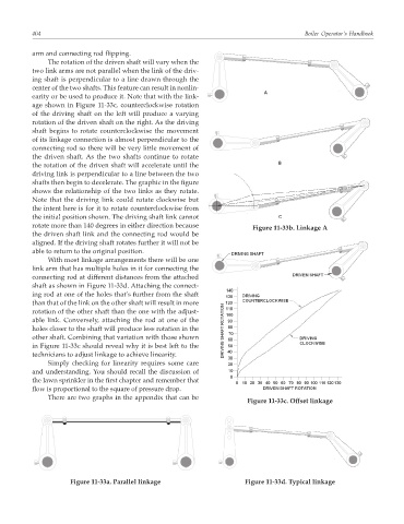
The rotation of the driven shaft will vary when the
two link arms are not parallel when the link of the driv-
ing shaft is perpendicular to a line drawn through the
center of the two shafts. This feature can result in nonlin-
earity or be used to produce it. Note that with the link-
age shown in Figure 11-33c, counterclockwise rotation
of the driving shaft on the left will produce a varying
rotation of the driven shaft on the right. As the driving
shaft begins to rotate counterclockwise the movement
of its linkage connection is almost perpendicular to the
connecting rod so there will be very little movement of
the driven shaft. As the two shafts continue to rotate
the rotation of the driven shaft will accelerate until the
driving link is perpendicular to a line between the two
shafts then begin to decelerate. The graphic in the figure
shows the relationship of the two links as they rotate.
Note that the driving link could rotate clockwise but
the intent here is for it to rotate counterclockwise from
the initial position shown. The driving shaft link cannot
rotate more than 140 degrees in either direction because
Figure 11-33b. Linkage A
the driven shaft link and the connecting rod would be
aligned. If the driving shaft rotates further it will not be
able to return to the original position.
With most linkage arrangements there will be one
link arm that has multiple holes in it for connecting the
connecting rod at different distances from the attached
shaft as shown in Figure 11-33d. Attaching the connect-
ing rod at one of the holes that’s further from the shaft
than that of the link on the other shaft will result in more
rotation of the other shaft than the one with the adjust-
able link. Conversely, attaching the rod at one of the
holes closer to the shaft will produce less rotation in the
other shaft. Combining that variation with those shown
in Figure 11-33c should reveal why it is best left to the
technicians to adjust linkage to achieve linearity.
Simply checking for linearity requires some care
and understanding. You should recall the discussion of
the lawn sprinkler in the first chapter and remember that
flow is proportional to the square of pressure drop.
There are two graphs in the appendix that can be
Figure 11-33c. Offset linkage
Figure 11-33a. Parallel linkage Figure 11-33d. Typical linkage