
Page 421 - Boiler_Operators_Handbook,_Second_Edition
P. 421
406 Boiler Operator’s Handbook
cam rotation, height, and flow then using that data to right and go back and check it.
note the required height. The data can be collected with I’m sometimes asked why I bother with the col-
whatever cam the manufacturer furnished. umns for zero percent signal. The answer is simple,
Before collecting cam data for linearity the stroke for some applications there has to be flow through the
of the valve or actuator should be established to provide valve or damper, like minimum flow of fuel and air for
120% of design flow. That extra flow provides an allow- a boiler. This positioner was set up for a feedwater con-
ance for the system to catch up. Some valve manufactur- trol valve and it has to shut for zero flow. The flow was
ers select their valves to produce 100% of the specified read by the feedwater flow meter and divided by the
flow rate at 70% of the valve opening which means the maximum flow to plot that curve in percent. The height
valve could pass 143% of design flow when full open; I of the new cam positions was calculated using the de-
believe that’s too much and is one reason I always select sired flow divided by the measured flow and multiplied
the trim of a control valve when I order it. Once the by the original height (in percent divided by 100). The
stroke is determined, adjust the linkage of the positioner heights are shown plotted on the blank cam of Figure
so it rotates the cam 100% of the design rotation at that 11-34c. A French curve (drafting instrument) is used to
stroke. Keep in mind, however, that the valve stroke draw a smooth curve on the cam as a guide for cutting it.
can’t be shortened excessively, it will have problems This may seem like a lot of work but it provides an accu-
at the bottom end and may jump on and off the seat, rate flow through the valve proportional to the signal so
because of the Bernoulli Effect, making control sloppy. a change in the control signal always produces a desired
It’s better to have
the trim replaced to
something smaller if
the stroke is reduced
more than 30%.
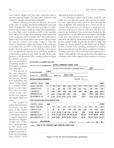
The record of
the valve character-
istic before and after
linearizing should
look something like
figure 11-34a which
is a sample align-
ment record sheet.
The cam rotation
relates to the valve
stroke and degrees
are simply values for
scale.
The graph of
actual measurements
(normally on the
back of the record
sheet) and marking
of the blank cam for
a sample alignment
are shown in Figures
11-34b and 11-34c.
Yes, I made mistakes
in the math and
that’s why the cam
graph is plotted so
I can see something
that doesn’t look Figure 11-34a. Record of linearizing a positioner