
Page 425 - Boiler_Operators_Handbook,_Second_Edition
P. 425
410 Boiler Operator’s Handbook
locations. The fan creates a lower pressure at the fan inlet the sensing ring.
by removing the air that enters it and it’s that void created There’s only one caveat with this method of air
by the fan removing the air that the room air rushes into. flow measurement. You have to be certain there’s no
The boiler room itself is nothing more than a big way for the air you’re measuring to go anywhere but to
pipe that the combustion air flows through; the fan inlet the burner. I’ve encountered more than one embarrass-
is just like an orifice. By measuring the static pressure ing situation where this method measured the air flow
at the orifice and subtracting it from the pressure in the but it didn’t all get to the burner. It won’t work if the
room we get the velocity pressure which tells us how there’s air leakage, branch ducts, or the like between fan
fast the air is flowing into the inlet of the fan. There’s one and burner.
thing rather nice about this flow measurement, there’s The original systems were a little lax in producing
no orifice coefficient because there’s no measurable fric- a true flow signal. Recall that the pressure drop we mea-
tion applied to the airstream between the boiler room sure is proportional to the square of the flow? Some sim-
and the fan inlet. ply used the differential signal and counted on the screw
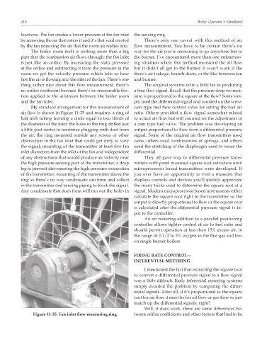
My standard arrangement for this measurement of cam type fuel flow control valve for setting the fuel air
air flow is shown in Figure 11-35 and requires: a ring of ratio. Others provided a flow signal somewhat related
half inch tubing forming a circle equal to two thirds of to actual air flow but still counted on the adjustment of
the diameter of the inlet; the holes in the ring drilled just a cam type fuel valve. The problem was developing an
a little past center to minimize plugging with dust from output proportional to flow from a differential pressure
the air; the ring mounted outside any screen or other signal. Some of the original air flow transmitters used
obstruction in the fan inlet that could get dirty to vary cams, others used combinations of springs, and others
the signal; mounting of the transmitter at least five fan used the stretching of the diaphragm used to sense the
inlet diameters from the inlet of the fan and independent differential.
of any obstructions that would produce air velocity near They all gave way to differential pressure trans-
the high pressure sensing port of the transmitter; a drop mitters with panel mounted square root extractors until
leg to prevent dirt entering the high pressure connection microprocessor based transmitters were developed. If
of the transmitter; mounting of the transmitter above the you ever have an opportunity to visit a museum that
ring so there’s no way condensate can form and collect displays controls and devices you’ll quickly appreciate
in the transmitter and sensing piping to block the signal. the many tricks used to determine the square root of a
Any condensate that does form will run out the holes in signal. Modern microprocessor based instruments either
calculate the square root right in the transmitter so the
output is directly proportional to flow or the square root
is calculated after the differential pressure signal is in-
put to the controller.
An air metering addition to a parallel positioning
controller allows tighter control of air to fuel ratio and
should permit operation at less than 15% excess air, in
the range of 2-1/2 to 3% oxygen in the flue gas and less
on single burner boilers.
FIRING RATE CONTROL—
INFERENTIAL METERING
I mentioned the fact that extracting the square root
to convert a differential pressure signal to a flow signal
was a little difficult. Early inferential metering systems
simply avoided the problem by comparing the differ-
ential signals. After all, if it’s proportional to the square
root for air flow it must be for oil flow or gas flow so just
match up the differential signals, right?
Well, it does work, there are some differences be-
Figure 11-35. Fan inlet flow measuring ring tween orifice coefficients and other factors that had to be