
Page 427 - Boiler_Operators_Handbook,_Second_Edition
P. 427
412 Boiler Operator’s Handbook
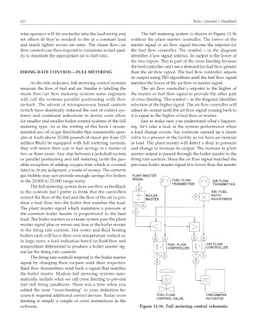
wise operator will let one boiler take the load swing and The full metering system is shown in Figure 11-36
set others (if they’re needed) to fire at a constant load without the plant master controller. The lower of the
and much tighter excess air rates. The steam flow/air master signal or air flow signal become the setpoint for
flow controls can then respond to variations in fuel qual- the fuel flow controller. The symbol < in the diagram
ity to maintain the appropriate air to fuel ratio. identifies a low signal selector, its output is the lower of
the two inputs. This is part of the cross limiting because
the fuel controller can’t see a demand for fuel flow greater
FIRING RATE CONTROL—FULL METERING than the air flow signal. The fuel flow controller adjusts
its output using PID algorithms until the fuel flow signal
As the title indicates, full metering control systems matches the lower of the air flow or master signal.
measure the flow of fuel and air. Similar to labeling the The air flow controller’s setpoint is the higher of
steam flow/air flow metering systems some engineers the master or fuel flow signal to provide the other part
will call the systems parallel positioning with flow of cross limiting. The symbol > in the diagram identifies
tie-back. The advent of microprocessor based controls selection of the higher signal. The air flow controller will
(which have drastically reduced the cost of control sys- adjust its output until the air flow signal coming back to
tems) and continued reductions in device costs allow it is equal to the higher of fuel flow or master.
for smaller and smaller boiler control systems of the full Just to make sure you understand what’s happen-
metering type. As of the writing of this book I recom- ing, let’s take a look at the system performance when
mended any oil or gas fired boiler that consistently oper- a load change occurs. Say someone opened up a steam
ates at loads above 25,000 pounds of steam per hour (25 valve to a process in the facility so we have an increase
million Btuh) be equipped with full metering controls; in load. The plant master will detect a drop in pressure
they will return their cost in fuel savings in a matter of and change to increase its output. The increase in plant
two or three years. Any step between a jackshaft system master output is passed through the boiler master to the
or parallel positioning and full metering (with the pos- firing rate controls. Since the air flow signal matched the
sible exception of adding oxygen trim which is covered previous boiler master signal it is lower than the master
later) is, in my judgment, a waste of money. The currernt
gas bubble may not provide enough savings for boilers
in the 20,000 to 25,000 range today.
The full metering system does use flow as feedback
to the controls but I prefer to think that the controllers
control the flow of the fuel and the flow of the air to pro-
duce a heat flow into the boiler that matches the load.
The plant master signal which maintains a pressure at
the common boiler header is proportional to the heat
load. The boiler masters in a steam system pass the plant
master signal plus or minus any bias at the boiler master
to the firing rate controls. Hot water and fluid heating
boilers each will have their own temperature control or,
in large sizes, a load indication based on fluid flow and
temperature differential to produce a boiler master sig-
nal for the firing rate controls.
The firing rate controls respond to the boiler master
signal by changing their outputs until their respective
fluid flow transmitters send back a signal that matches
the boiler master. Modern full metering systems auto-
matically include what we call cross limiting to prevent
fuel rich firing conditions. There was a time when you
added the term “cross-limiting” to your definition be-
cause it required additional control devices. Today cross
limiting is simply a couple of extra instructions in the
software. Figure 11-36. Full metering control schematic