
Page 418 - Boiler_Operators_Handbook,_Second_Edition
P. 418
Controls 403
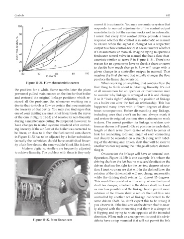
correct it in automatic. You may encounter a system that
responds to manual adjustments of the control output
unsatisfactorily but the system works well in automatic.
I insist that every flow control device provide a linear
response whether the control is in automatic or manual
to ensure when the signal is changed for a respective
output to a flow control device it doesn’t matter whether
it’s in automatic or manual. Imagine trying to operate a
feedwater control valve in manual that has a flow char-
acteristic similar to curve F in Figure 11-31. There’s no
reason for an operator to have to check a chart or curve
to decide how much change in flow will occur with a
given change in a controller output in manual. That
requires the final element that actually changes the flow
produce the linear characteristic.
Figure 11-31. Flow characteristic curves When working on anything that controls flow the
first thing to think about is retaining linearity. It’s not
the problem for a while. Some months later the plant
at all uncommon for an operator or maintenance man
personnel pulled maintenance on the fan for that boiler
to wonder why linkage is arranged as it is and change
and restored the original linkage positions which re-
it so it “looks right.” Adjusting the position of linkage
stored all the problems. So, whenever working on a
on a boiler can alter the fuel air relationship. This has
device that controls a flow be certain that you maintain
happened many times with different degrees of disas-
the linearity of that device. You may also find signs that
trous consequences. Before dismantling any linkage,
one of your existing systems is not linear (note the curve
including ones that aren’t on boilers, always mark it
of the cam in Figure 11-32) and resolve its non-linearity
and restore its original position after maintenance work
during a maintenance outing. Be prepared, however, to
is done. The correct position for linkage is seldom uni-
have changes in related systems resolved after correct-
form as shown in Figure11-33a so position on each shaft,
ing linearity. If the air flow of the boiler was corrected to
length of shaft arms (from center of shaft to center of
be linear, or close to it, then the fuel control cam shown
hole for connecting rod) and length of each connecting
in Figure 11-32 has to be adjusted by a boiler technician
rod should be recorded on a sketch along with label-
(actually the technician should have established linear-
ing of the driving and driven shaft that will be clear to
ity of air flow first so the cam wouldn’t look like it does).
another worker replacing the linkage all before disman-
Modern digital controllers are frequently adjusted
tling it.
to achieve linearity. The problem with them is they only
On occasion the linkage will have an unusual con-
figuration, Figure 11-33b is one example. It’s where the
driving shaft on the left has no measurable effect on the
driven shaft on the right for the last few degrees of rota-
tion. I trust you can see that within the dashed lines the
rotation of the driven shaft will not change measurably
while the driving shaft rotates for almost 15 degrees.
This would be consistent with a setup where the forced
draft fan damper, attached to the driven shaft, is closed
as much as possible and the linkage has to permit more
rotation of the driven shaft to reduce the fuel flow rate
controlled by another set of linkage connected to the
same driven shaft. So, don’t expect this to be wrong if
you observe it. If the link arm on the driven shaft is near-
ly aligned with the connecting rod there is a danger of
it flipping and trying to rotate opposite of the intended
direction. When such an arrangement is used it’s advis-
Figure 11-32. Non linear cam able to have a stop mounted that will not permit the link