
Page 415 - Boiler_Operators_Handbook,_Second_Edition
P. 415
400 Boiler Operator’s Handbook
The controls are all linked to the one common shaft marked with the corresponding pressure or tempera-
so fuel and air flow controlling devices are all positioned ture. Occasionally you will find a reset controller power-
together. Some people will call this system mechanical ing an actuator to position a jackshaft.
parallel positioning but I call them jackshaft systems. The first step in setting up controls with a jackshaft
To maintain a pressure or fluid temperature the is to establish linearity of air flow. That’s all you have to
modulating motor aligns its potentiometer with the do to get linear control because the fuel will be adjusted
pressuretrol or temperature controller as described ear- to match air flow. With simple linkage like that shown
lier. The movement of the motor changes the position in Figures 11-26 and 11-29 establishing linearity can be
of the fuel flow control valve to increase or decrease the very difficult but it’s an exercise that’s essential to get
quantity of fuel entering the burner and, therefore, the consistent control. I’ll cover it in more detail in a bit.
heat released in the furnace and transferred to the fluid After establishing linearity, tuning consists of posi-
and vapor inside the pressure vessel. This is commonly tioning the controls at each screw on the fuel valve (Fig-
a proportional control. You should be able to mount a ure 11-27 or 11-28) then adjusting the screw to increase
lever on the jackshaft and a scale at the end of the lever or decrease actual fuel flow at that position until the
desired air to fuel ratio is established.
That process should be repeated at each screw al-
though some technicians will do every other one or ev-
ery third one then adjust the ones in between to provide
a smooth transition from screw to screw. Sometimes
the screws are not evident, they’re concealed beneath a
cover (Figure 11-30) to provide some tamper resistance.
The series of screws form a cam that the roller on the fuel
control valve shaft rides on as the jackshaft rotates. With
some difficulty you can usually position yourself where
you can see the shape of that cam.
I’ve seen a number of those cams adjusted in a
manner that they look more like a woman’s figure than
a smooth cam. Look at yours to see if it’s a smooth
transition from low fire to high fire. If it isn’t then the
system is probably non-linear. You may have trouble
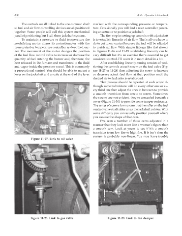
Figure 11-27. Link to oil valve
Figure 11-28. Link to gas valve Figure 11-29. Link to fan damper