
Page 239 - Buried Pipe Design
P. 239
Design of Pressure Pipes 213
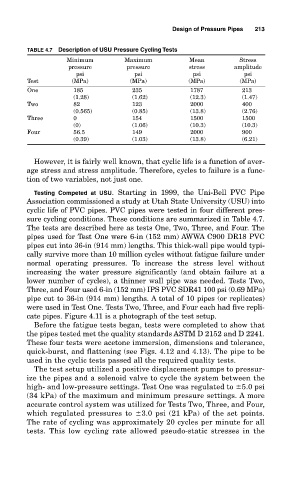
TABLE 4.7 Description of USU Pressure Cycling Tests
Minimum Maximum Mean Stress
pressure pressure stress amplitude
psi psi psi psi
Test (MPa) (MPa) (MPa) (MPa)
One 185 235 1787 213
(1.28) (1.62) (12.3) (1.47)
Two 82 123 2000 400
(0.565) (0.85) (13.8) (2.76)
Three 0 154 1500 1500
(0) (1.06) (10.3) (10.3)
Four 56.5 149 2000 900
(0.39) (1.03) (13.8) (6.21)
However, it is fairly well known, that cyclic life is a function of aver-
age stress and stress amplitude. Therefore, cycles to failure is a func-
tion of two variables, not just one.
Testing Competed at USU. Starting in 1999, the Uni-Bell PVC Pipe
Association commissioned a study at Utah State University (USU) into
cyclic life of PVC pipes. PVC pipes were tested in four different pres-
sure cycling conditions. These conditions are summarized in Table 4.7.
The tests are described here as tests One, Two, Three, and Four. The
pipes used for Test One were 6-in (152 mm) AWWA C900 DR18 PVC
pipes cut into 36-in (914 mm) lengths. This thick-wall pipe would typi-
cally survive more than 10 million cycles without fatigue failure under
normal operating pressures. To increase the stress level without
increasing the water pressure significantly (and obtain failure at a
lower number of cycles), a thinner wall pipe was needed. Tests Two,
Three, and Four used 6-in (152 mm) IPS PVC SDR41 100 psi (0.69 MPa)
pipe cut to 36-in (914 mm) lengths. A total of 10 pipes (or replicates)
were used in Test One. Tests Two, Three, and Four each had five repli-
cate pipes. Figure 4.11 is a photograph of the test setup.
Before the fatigue tests began, tests were completed to show that
the pipes tested met the quality standards ASTM D 2152 and D 2241.
These four tests were acetone immersion, dimensions and tolerance,
quick-burst, and flattening (see Figs. 4.12 and 4.13). The pipe to be
used in the cyclic tests passed all the required quality tests.
The test setup utilized a positive displacement pumps to pressur-
ize the pipes and a solenoid valve to cycle the system between the
high- and low-pressure settings. Test One was regulated to 5.0 psi
(34 kPa) of the maximum and minimum pressure settings. A more
accurate control system was utilized for Tests Two, Three, and Four,
which regulated pressures to 3.0 psi (21 kPa) of the set points.
The rate of cycling was approximately 20 cycles per minute for all
tests. This low cycling rate allowed pseudo-static stresses in the