
Page 42 - Buried Pipe Design
P. 42
20 Chapter Two
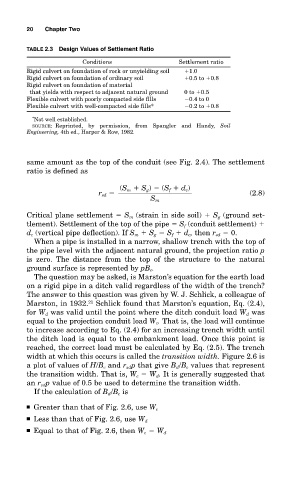
TABLE 2.3 Design Values of Settlement Ratio
Conditions Settlement ratio
Rigid culvert on foundation of rock or unyielding soil 1.0
Rigid culvert on foundation of ordinary soil 0.5 to 0.8
Rigid culvert on foundation of material
that yields with respect to adjacent natural ground 0 to 0.5
Flexible culvert with poorly compacted side fills 0.4 to 0
Flexible culvert with well-compacted side fills* 0.2 to 0.8
* Not well established.
SOURCE: Reprinted, by permission, from Spangler and Handy, Soil
Engineering, 4th ed., Harper & Row, 1982.
same amount as the top of the conduit (see Fig. 2.4). The settlement
ratio is defined as
(S m S g ) (S f d c )
r sd (2.8)
S m
Critical plane settlement S m (strain in side soil) S g (ground set-
tlement). Settlement of the top of the pipe S f (conduit settlement)
d c (vertical pipe deflection). If S m S g S f d c , then r sd 0.
When a pipe is installed in a narrow, shallow trench with the top of
the pipe level with the adjacent natural ground, the projection ratio p
is zero. The distance from the top of the structure to the natural
ground surface is represented by pB c .
The question may be asked, is Marston’s equation for the earth load
on a rigid pipe in a ditch valid regardless of the width of the trench?
The answer to this question was given by W. J. Schlick, a colleague of
Marston, in 1932. 21 Schlick found that Marston’s equation, Eq. (2.4),
for W d was valid until the point where the ditch conduit load W d was
equal to the projection conduit load W c . That is, the load will continue
to increase according to Eq. (2.4) for an increasing trench width until
the ditch load is equal to the embankment load. Once this point is
reached, the correct load must be calculated by Eq. (2.5). The trench
width at which this occurs is called the transition width. Figure 2.6 is
a plot of values of H/B c and r sd p that give B d /B c values that represent
the transition width. That is, W c W d . It is generally suggested that
an r sd p value of 0.5 be used to determine the transition width.
If the calculation of B d /B c is
■ Greater than that of Fig. 2.6, use W c
■ Less than that of Fig. 2.6, use W d
■ Equal to that of Fig. 2.6, then W c W d