
Page 160 - Cam Design Handbook
P. 160
THB5 8/15/03 1:53 PM Page 148
148 CAM DESIGN HANDBOOK
10
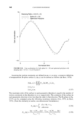
Damping Ratio = 0.2 (C = C)
Spline (k = 10)
Optimized Polydyne
Cam acceleration 0
–10
0 .5 1
Normalized time
FIGURE 5.32. Cam accelerations for both spline (k = 10) and optimized polydyne with
damping ratio = 0.2 (C s = C f ) in Example 8.
Assuming the motion constraints are defined in an n ¥ m array, a recursive definition
of nonparametric B-spline surface S 1 (f 2 ,s 2 ) can be defined as follows (de Boor, 1978):
n m
S f , ) = ÂÂ N () M j k 2 ( s p ) i j
(
s
f
2
2
,
1
2
,
2
,
ik 1
=
=
i 1 j 1
2 £ k £ n
1
2 £ k £ m. (5.37)
2
The maximum order of the surface in each parametric direction is equal to the number of
motion constraints in that direction (n or m, respectively). The continuity of the surface in
each parametric direction is two less than the order in that direction. The B-splines in Eq.
(5.37) can be computed using the following recurrence relations (Cox, 1972; de Boor,
1972). (Note the similarity to earlier, one-dimensional formulations.)
1 Ï if x £ f < x +
f
N () = Ì i 2 i 1 (5.38)
i,1 2
Ó 0 otherwise
( f - xN ) f () x ( - f N ) f ()
-
+
+
-
N () = 2 i i k , 1 1 2 + ik 1 2 i 1 k , 1 1 2 (5.39)
f
x - x x - x
ik , 1 2
+
+-
+
ik 1 1 i ik 1 i 1