
Page 158 - Cam Design Handbook
P. 158
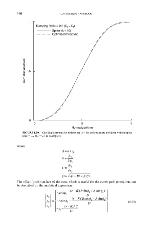
THB5  8/15/03  1:53 PM  Page 146

          146                      CAM DESIGN HANDBOOK

                 1
                     Damping Ratio = 0.2 (C = C ) f
                                      s
                              Spline (k = 10)
                              Optimized Polydyne


               Cam displacement  .5


                 0
                    0                        .5                          1
                                         Normalized time
             FIGURE 5.30.  Cam displacements for both spline (k = 10) and optimized polydyne with damping
             ratio = 0.2 (C s = C f) in Example 8.


          where
                                     ∫+
                                   Aa s   1
                                       ∂  s
                                   B ∫  1
                                      ∂f
                                         2
                                       ∂  s
                                   C ∫  1
                                      ∂  s 2
                                         2
                                   D ∫  A +  B +  A C .
                                             2
                                                2
                                                  2
          The offset (pitch) surface of the cam, which is useful for the cutter path generation, can
          be described by the analytical expression
                                           R Bsinf
                               Ï Acosf  -  ( r - )(  2  +  Acosf 2 )  ¸
                               Ô     2                      Ô
                          Ï x ¸                  D
                            R
                                            R Bcosf
                                                            Ô
                          Ô  Ô  Ô Ô      ( r - )(   -  Asinf  ) Ô
                               Ì
                          Ì y ˝ = - Asinf 2  -     2      2  ˝          (5.35)
                            R
                          Ô  Ô  Ô                 D         Ô
                           z Ó  R ˛  Ô  ( r - )             Ô
                                        R AC
                               Ô Ó  s --  D                 Ô
                                  2
                                                            ˛