
Page 157 - Cam Design Handbook
P. 157
THB5 8/15/03 1:53 PM Page 145
CAM MOTION SYNTHESIS USING SPLINE FUNCTIONS 145
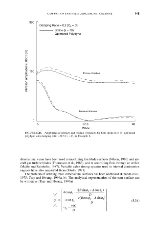
300
Damping Ratio = 0.2 (C = C )
f
s
Spline (k = 10)
Optimized Polydyne
Vibration amplitudes x .0001 (in) 150 Primary Vibration
Residual Vibration
0
5 22.5 40
Wn/w
FIGURE 5.29. Amplitudes of primary and residual vibrations for both spline (k = 10) optimized
polydyne with damping ratio = 0.2 (C s = C f ) in Example 8.
dimensional cams have been used in machining fan blade surfaces (Nilson, 1980) and air-
craft gas turbine blades (Thompson et al., 1983), and in controlling flow through an orifice
(Mabie and Reinholtz, 1987). Variable valve timing systems used in internal combustion
engines have also employed them (Titolo, 1991).
The problem of defining three-dimensional surfaces has been addressed (Dhande et al.,
1975; Tsay and Hwang, 1994a, b). The analytical representation of the cam surface can
be written as (Tsay and Hwang, 1994a)
Ï Acosf - rB ( sinf 2 + Acosf 2 ) ¸
Ô 2 Ô
Ï x ¸ D
Ô Ô Ô Ô rB ( cosf 2 - Asinf 2 ) Ô
Ô
Ì y ˝ = - Asinf 2 - ˝ (5.34)
Ì
Ô Ô Ô D Ô
z Ó ˛ rAC
Ô s -- Ô
Ô Ó 2 D Ô
˛