
Page 152 - Cam Design Handbook
P. 152
THB5 8/15/03 1:52 PM Page 140
140 CAM DESIGN HANDBOOK
designer. For instance, selection of the collocation points is readily automated. Such
operations are described in the example, however, for the sake of thoroughness.
Synthesis of the Output Motion In this illustration the basic goal is to satisfy the ten
basic constraints at t = 0 and at t = 1 in the list of constraints that follows. These con-
straints are the primary design constraints. The two additional constraints at t = 0.5 were
added in the iterative process to refine the motion somewhat.
Since the degree of the spline curve is k - 1, splines of order k = 6 are required for S (4)
(4)
to be continuous. It is necessary to achieve this continuity if the constraints on S are to
be satisfied, as they must be if continuous cam acceleration is to be obtained.
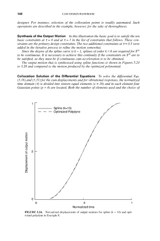
The output motion that is synthesized using spline functions is shown in Figures 5.24
to 5.28 and compared to the motion produced by the optimized polynomial.
Collocation Solution of the Differential Equations To solve the differential Eqs.
(5.18) and (5.31) for the cam displacements and for vibrational responses, the normalized
time domain (t) is divided into sixteen equal elements (e = 16) and in each element four
Gaussian points (p = 4) are located. Both the number of elements used and the choice of
1
Spline (k=10)
Optimized Polydyne
Displacement of output motion .5
0
0 .5 1
Normalized time
FIGURE 5.24. Normalized displacements of output motions for spline (k = 10) and opti-
mized polydyne in Example 8.