
Page 155 - Cam Design Handbook
P. 155
THB5 8/15/03 1:53 PM Page 143
CAM MOTION SYNTHESIS USING SPLINE FUNCTIONS 143
80
Jerk of output motion 0
Spline (k = 10)
Optimized Polydyne
–80
0 .5 1
Normalized time
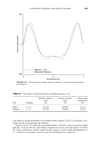
FIGURE 5.27. Normalized jerk of output motions for spline (k = 10) and optimized polydyne
in Example 8.
TABLE 5.7 Peak Values of Dynamic Response with Damping Ratio = 0.2
Residual vibration Primary vibration Interior peak
peak peak contact force
Case Damping (in) (in) (lb)
Spline C f = C S 0.01181 0.01539 213.42
Polydyne C f = C s 0.01220 0.01604 216.38
cam motion is easily determined as described earlier. Figures 5.24 to 5.32 provide a con-
venient means of interpreting the outcome.
Figures 5.30 to 5.32 show the cam displacements, velocities, and accelerations found
from Eq. (5.18) for the two cases being compared. It can be seen from Figure 5.32 that
the cam accelerations of these output motions appear to have small discontinuities at
t = 1. However, the motion carried on into the dwell period is continuous.