
Page 159 - Cam Design Handbook
P. 159
THB5 8/15/03 1:53 PM Page 147
CAM MOTION SYNTHESIS USING SPLINE FUNCTIONS 147
3
Damping Ratio = 0.2 (C = C ) f
s
Spline (k = 10)
Optimized Polydyne
Cam velocity 1.5
0
0 .5 1
Normalized time
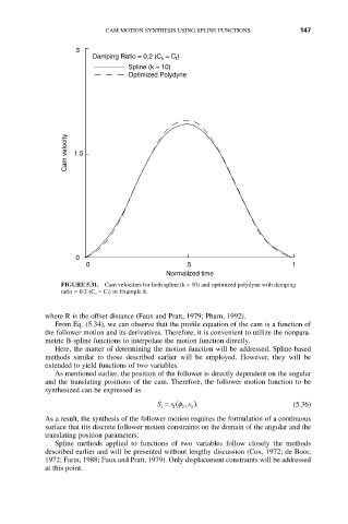
FIGURE 5.31. Cam velocities for both spline (k = 10) and optimized polydyne with damping
ratio = 0.2 (C s = C f ) in Example 8.
where R is the offset distance (Faux and Pratt, 1979; Pharn, 1992).
From Eq. (5.34), we can observe that the profile equation of the cam is a function of
the follower motion and its derivatives. Therefore, it is convenient to utilize the nonpara-
metric B-spline functions to interpolate the motion function directly.
Here, the matter of determining the motion function will be addressed. Spline-based
methods similar to those described earlier will be employed. However, they will be
extended to yield functions of two variables.
As mentioned earlier, the position of the follower is directly dependent on the angular
and the translating positions of the cam. Therefore, the follower motion function to be
synthesized can be expressed as
s
S = (f , s ). (5.36)
1
2
2
1
As a result, the synthesis of the follower motion requires the formulation of a continuous
surface that fits discrete follower motion constraints on the domain of the angular and the
translating position parameters.
Spline methods applied to functions of two variables follow closely the methods
described earlier and will be presented without lengthy discussion (Cox, 1972; de Boor,
1972; Farin, 1988; Faux and Pratt, 1979). Only displacement constraints will be addressed
at this point.