
Page 216 - Cam Design Handbook
P. 216
THB7 8/15/03 1:58 PM Page 204
204 CAM DESIGN HANDBOOK
7.6 CASE STUDIES
We introduce below two case studies illustrating the application of the concepts introduced
in this chapter.
7.6.1 Cam-Size Minimization
We illustrate here a methodology that allows the designer to minimize the overall size of
planar cam mechanisms while maintaining an acceptable force-transmission performance
on imposing bounds on the pressure angle. This methodology has some improvements
over other techniques, e.g., the exploratory search method proposed in Chan and Kok
(1996).
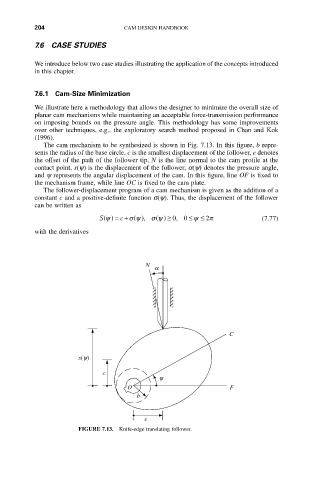
The cam mechanism to be synthesized is shown in Fig. 7.13. In this figure, b repre-
sents the radius of the base circle, c is the smallest displacement of the follower, e denotes
the offset of the path of the follower tip, N is the line normal to the cam profile at the
contact point, s(y) is the displacement of the follower, a(y) denotes the pressure angle,
and y represents the angular displacement of the cam. In this figure, line OF is fixed to
the mechanism frame, while line OC is fixed to the cam plate.
The follower-displacement program of a cam mechanism is given as the addition of a
constant c and a positive-definite function s(y). Thus, the displacement of the follower
can be written as
c
0
s y
S y () =+ (), s y () ≥ , 0 £ y £ 2 p (7.77)
with the derivatives
N
a
C
s(y)
c
y
O F
b
e
FIGURE 7.13. Knife-edge translating follower.