
Page 219 - Cam Design Handbook
P. 219
THB7 8/15/03 1:58 PM Page 207
GEOMETRY OF PLANAR CAM PROFILES 207
e
30°
30°
67.54 mm
c
–11.55 mm
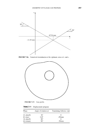
FIGURE 7.16. Numerical determination of the optimum values of c and e.
FIGURE 7.17. Cam profile.
TABLE 7.1 Displacement program
Phase Angle of rotation y Translating follower s(y)
D 1 (dwell) 36° 0
R 1 (rise) 144° +50mm
D 2 (dwell) 90° 0
R 2 (return) 90° -50mm