
Page 222 - Cam Design Handbook
P. 222
THB7 8/15/03 1:58 PM Page 210
210 CAM DESIGN HANDBOOK
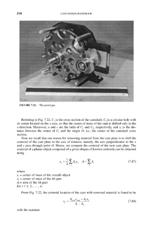
FIGURE 7.21. The prototype.
Referring to Fig. 7.22, C 1 is the cross section of the camshaft; C 2 is a circular hole with
its center located on the x-axis, so that the center of mass of the cam is shifted only in the
x-direction. Moreover, a and c are the radii of C 1 and C 2, respectively, and x 2 is the dis-
tance between the center of C 2 and the origin O, i.e., the center of the camshaft cross
section.
Now we recall that our reason for removing material from the cam plate is to shift the
centroid of the cam plate to the axis of rotation, namely, the axis perpendicular to the x
and y axes through point O. Hence, we compute the centroid of the new cam plate. The
centroid of a planar object composed of n given shapes of known centroids can be obtained
using
1 n n
x = Â Ax , A = Â A (7.87)
c i i i
A i=1 1
where
x c = center of mass of the overall object
x i = center of mass of the ith part
A i = area of the ith part
for i = 1, 2,..., n.
From Fig. 7.22, the centroid location of the cam with removed material is found to be
Ax - A x
x = cam cam 2 2 (7.88)
c
A - A
c 2
with the notation