
Page 224 - Cam Design Handbook
P. 224
THB7 8/15/03 1:58 PM Page 212
212 CAM DESIGN HANDBOOK
2
rt cam cam w c cam
A
2
rt A w c cw 1
cw cw
d 1 d 2 d 3 d 2 d 1
w
O B
f O f B
2
rt A w c cw 2
cw cw
2
rt cam cam w c cam
A
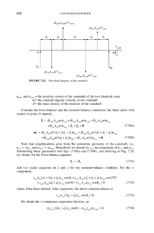
FIGURE 7.23. Free-body diagram of the camshaft.
= the position vectors of the centroids of the two identical cams
c cam 1 and c cam 2
w = the constant angular velocity of the camshaft
d = the mass density of the material of the camshaft
Consider the force-balance and the moment-balance conditions, the latter taken with
respect to point O, namely,
f = d t A w 2 c + t d A w 2 c +d t A w 2 c
s cam cam cam cam cam cam cw cw cw 1
+d tA w 2 c cw 2 + f + f = 0 (7.90a)
cw
cw
B
O
m = d tA w 2 ( d + 2 d + d c ) + t d A w 2 ( d + d + d c )
s cw cw 1 2 3 cw 1 cam cam 1 2 3 cam
+d t cam A w 2 ( d + d 2 c ) cam +d t A w 2 d 1 c cw 2 = 0. (7.90b)
cw
1
cw
cam
Note that simplifications arise from the symmetric geometry of the camshaft, i.e.,
.
c cw 1 =-c cw 2 and c cam 1 =-c cam 2 . Henceforth we denote by c cw the magnitude of c cw 1 and c cw 2
Substituting these parameters into Eqs. (7.90a) and (7.90b), and referring to Fig. 7.24,
we obtain, for the force-balance equation,
f =- f B (7.91)
O
and two scalar equations in x and y for the moment-balance condition. For the x-
component,
t A ( d + 2 d + dc ) cosq + t A ( d + d + dc ) cos 270 ∞
cw cw 1 2 3 cw 1 cam cam 1 2 3 cam
+ t cam A ( d + d c ) cam cos 900 (7.92)
∞+
t A d c cosq
=
cw
1
cw 1
cam
cw
2
2
where d has been deleted. After expansion, the above relation reduces to
tA ( 2 d + d c ) cw cosq 1 = 0. (7.93)
cw
2
cw
3
We obtain the y-component expression likewise, as
At ( 2 d + d c ) cw sinq 1 - A t d c cam = 0. (7.94)
cw cw
cam cam 3
2
3