
Page 221 - Cam Design Handbook
P. 221
THB7 8/15/03 1:58 PM Page 209
GEOMETRY OF PLANAR CAM PROFILES 209
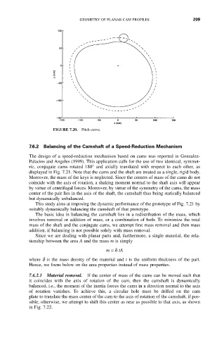
FIGURE 7.20. Pitch curve.
7.6.2 Balancing of the Camshaft of a Speed-Reduction Mechanism
The design of a speed-reduction mechanism based on cams was reported in Gonzalez-
Palacios and Angeles (1999). This application calls for the use of two identical, symmet-
ric, conjugate cams rotated 180° and axially translated with respect to each other, as
displayed in Fig. 7.21. Note that the cams and the shaft are treated as a single, rigid body.
Moreover, the mass of the keys is neglected. Since the centers of mass of the cams do not
coincide with the axis of rotation, a shaking moment normal to the shaft axis will appear
by virtue of centrifugal forces. Moreover, by virtue of the symmetry of the cams, the mass
center of the pair lies in the axis of the shaft, the camshaft thus being statically balanced
but dynamically unbalanced.
This study aims at imposing the dynamic performance of the prototype of Fig. 7.21 by
suitably dynamically balancing the camshaft of that prototype.
The basic idea in balancing the camshaft lies in a redistribution of the mass, which
involves removal or addition of mass, or a combination of both. To minimize the total
mass of the shaft and the conjugate cams, we attempt first mass removal and then mass
addition, if balancing is not possible solely with mass removal.
Since we are dealing with planar parts and, furthermore, a single material, the rela-
tionship between the area A and the mass m is simply
m =d tA
where d is the mass density of the material and t is the uniform thickness of the part.
Hence, we focus below on the area properties instead of mass properties.
7.6.2.1 Material removal. If the center of mass of the cams can be moved such that
it coincides with the axis of rotation of the cam, then the camshaft is dynamically
balanced, i.e., the moment of the inertia forces the cams in a direction normal to the axis
of rotation vanishes. To achieve this, a circular hole must be drilled on the cam
plate to translate the mass center of the cam to the axis of rotation of the camshaft, if pos-
sible; otherwise, we attempt to shift this center as near as possible to that axis, as shown
in Fig. 7.22.