
Page 225 - Cam Design Handbook
P. 225
THB7 8/15/03 1:58 PM Page 213
GEOMETRY OF PLANAR CAM PROFILES 213
y
m
cam 1
m
cw 1
c
q 1 cam 1
q
2 x
c
cw 1
c
cw 2
c
cam 2
m
cw 2
m
cam 2
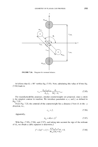
FIGURE 7.24. Diagram for moment balance.
It follows that q 1 = 90° verifies Eq. (7.93). Now, substituing this value of q into Eq.
(7.94) leads to
At c d
c cw = cam cam cam 3 c cam . (7.95)
At 2 d + d 3
cw cw
2
For manufacturability purposes, circular counterweights are proposed, since a circle
is the simplest contour to machine. We introduce parameters a, e, and f, as defined in
Fig. 7.25.
From Fig. 7.25, the centroid of the counterweight lies a distance f from O, in the -y
direction, i.e.,
c = f . (7.96)
cw
Apparently,
f
A = ( p e + ) 2 (7.97)
cw
With Eqs. (7.95), (7.96), and (7.97), and taking into account the sign of the ordinate
of O 2, we obtain a cubic equation to determine f:
dA t c
f + 2 ef + e f - 3 cam cam cam = 0. (7.98)
2
2
3
p t ( 2 d + d )
cw 2 3