
Page 223 - Cam Design Handbook
P. 223
THB7 8/15/03 1:58 PM Page 211
GEOMETRY OF PLANAR CAM PROFILES 211
y
C 2
C
a c
c
x
O
C 1
t 2
b
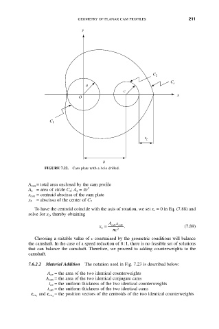
FIGURE 7.22. Cam plate with a hole drilled.
A cam = total area enclosed by the cam profile
A 2 = area of circle C 2; A 2 = pc 2
x cam = centroid abscissa of the cam plate
x 2 = abscissa of the center of C 2
To have the centroid coincide with the axis of rotation, we set x c = 0 in Eq. (7.88) and
solve for x 2, thereby obtaining
Ax
x = cam cam . (7.89)
2
c p 2
Choosing a suitable value of c constrained by the geometric conditions will balance
the camshaft. In the case of a speed reduction of 8:1, there is no feasible set of solutions
that can balance the camshaft. Therefore, we proceed to adding counterweights to the
camshaft.
7.6.2.2 Material Addition The notation used in Fig. 7.23 is described below:
A cw = the area of the two identical counterweights
A cam = the area of the two identical conjugate cams
t cw = the uniform thickness of the two identical counterweights
t cam = the uniform thickness of the two identical cams
= the position vectors of the centroids of the two identical counterweights
c cw 1 and c cw 2