Page 218 - Cam Design Handbook
P. 218

THB7  8/15/03  1:58 PM  Page 206

          206                      CAM DESIGN HANDBOOK

                               e
                    a m

                                                                 a M
                               h 1


                               e opt


                                               c opt                c
                               h 2


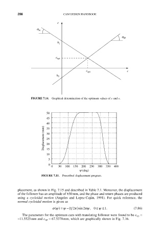
                 FIGURE 7.14.  Graphical determination of the optimum values of c and e.


                          50
                          45
                          40
                        Displacement (mm)  30
                          35

                          25
                          20
                          15
                          10
                           5
                           0
                            0   50  100  150  200  250  300  350  400
                                           y (deg)
                       FIGURE 7.15.  Prescribed displacement program.


          placement, as shown in Fig. 7.15 and described in Table 7.1. Moreover, the displacement
          of the follower has an amplitude of ±50mm, and the phase and return phases are produced
          using  a  cycloidal  motion (Angeles  and  Lopez-Cajún,  1991).  For  quick  reference,  the
          normal cycloidal motion is given as
                                                    £
                             s y () = y -(12 p)sin 2 py,  01.           (7.86)
                                                     y £
             The parameters for the optimum cam with translating follower were found to be e opt =
          -11.5525mm and c opt = 67.5378mm, which are graphically shown in Fig. 7.16.
   213   214   215   216   217   218   219   220   221   222   223