
Page 245 - Carbon Nanotube Fibres and Yarns
P. 245
Sensors based on CNT yarns 235
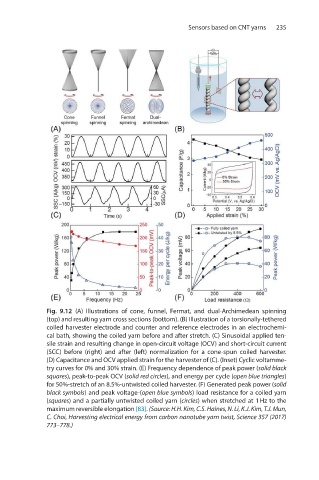
Fig. 9.12 (A) Illustrations of cone, funnel, Fermat, and dual-Archimedean spinning
(top) and resulting yarn cross sections (bottom). (B) Illustration of a torsionally-tethered
coiled harvester electrode and counter and reference electrodes in an electrochemi-
cal bath, showing the coiled yarn before and after stretch. (C) Sinusoidal applied ten-
sile strain and resulting change in open-circuit voltage (OCV) and short-circuit current
(SCC) before (right) and after (left) normalization for a cone-spun coiled harvester.
(D) Capacitance and OCV applied strain for the harvester of (C). (Inset) Cyclic voltamme-
try curves for 0% and 30% strain. (E) Frequency dependence of peak power (solid black
squares), peak-to-peak OCV (solid red circles), and energy per cycle (open blue triangles)
for 50%-stretch of an 8.5%-untwisted coiled harvester. (F) Generated peak power (solid
black symbols) and peak voltage-(open blue symbols) load resistance for a coiled yarn
(squares) and a partially untwisted coiled yarn (circles) when stretched at 1 Hz to the
maximum reversible elongation [83]. (Source: H.H. Kim, C.S. Haines, N. Li, K.J. Kim, T.J. Mun,
C. Choi, Harvesting electrical energy from carbon nanotube yarn twist, Science 357 (2017)
773–778.)