
Page 171 - Chemical Process Equipment - Selection and Design
P. 171
7.5. EQUIPMENT FOR GAS TRANSPORT 143
Head in feet of 50-1000atm or more. Some performance data are shown in
500
, 25 150 175 ~i00(~50)200~250(300~400~500~Above Figure 7.5.
Diaphragm pumps [Fig. 7.12(i)] also produce pulsating flow.
20 They are applied for small flow rates, less than 100 gpm or so, often
40 for metering service. Their utility in such applications overbalances
75
E the drawback of their intrinsic low efficiencies, of the order of 20%.
& 200 Eifher single or Screw pumps [Fig. 7.12(g)] are suited for example to high
5 400 double suction viscosity polymers and dirty liquids at capacities up to 2000 gpm and
vj
.- e 600 pressures of 200 atm at speeds up to 3000 rpm. They are compact,
2 1000 quiet, and efficient. Figure 7.4(d) shows typical performance data.
.-
8 2000 Gear pumps [Figs. 7.12(e) and (f)] are best suited to handling
QQ 2500 clear liquids at a maximum of about 1000 gpm at 150 atm. Typical
'J 4000 performance curves are shown in Figure 7.41~).
6000 Doub/e suction
Peristaltic pumps [Fig. 7.12(h)] move the liquid by squeezing a
8800 tube behind it with a rotor. Primarily they are used as metering
~0,000 pumps at low capacities and pressures in corrosive and sanitary
(a) services when resistant flexible tubes such as those of deflon can be
used, and in laboratories.
Turbine pumps [Figs. 7.9(f), 7.12(i), and 7.4(a)] also are called
regenerative or peripheral. They are primarily for small capacity
and high pressure service. In some ranges they are more efficient
than centrifugals. Because of their high suction lifts they are suited
to handling volatile liquids. They are not suited to viscous liquids or
abrasive slurries.
5.5. EQUIPMENT FOR GAS TRANSPORT
Gas handling equipment is used to transfer materials through pipe
lines, during which just enough pressure or head is generated to
overcome line friction, or to raise or lower the pressure to some
required operating level in connected process equipment. The main
classes of this kind of equipment are illustrated in Figures 7.18 and
7.19 and are described as follows.
U S gallons per minute
(b) 1. Fans accept gases at near atmospheric pressure and raise the
pressure by approximately 3% (12in. of water), usually on air
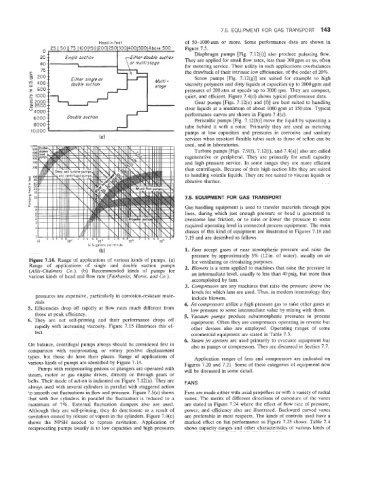
Figure 7.14. Range of applications of various kinds of pumps. (a) for ventilating or circulating purposes.
Range of applications of singIe and double suction pumps 2. Blowers is a term applied to machines that raise the pressure to
(Allis-Chalmers Co.). (b) Recommended kinds of pumps for an intermediate level, usually to less than 40 psig, but more than
various kinds of head and flow rate (Fairbanks, Morse, and Co.).
accomplished by fans.
a. Compressors are any machines that raise the pressure above the
levels for which fans are used. Thus, in modern terminology they
pressures are expensive, particularly in corrosion-resistant mate- include blowers.
rials. 4. Jet compressors utilize a high pressure gas to raise other gases at
5. Efficiencies drop off rapidly at flow rates much different from low pressure to some intermediate value by mixing with them.
those at peak efficiency. 5. Vacuum pumps produce subatmospheric pressures in process
6. They are not self-priming and their performance drops off equipment. Often they are compressors operating in reverse but
rapidly with increasing viscosity. Figure 7.15 illustrates this ef- other devices also are employed. Operating ranges of some
fect. commercial equipment are stated in Table 7.3.
6. Steam jet ejectors are used primarily to evacuate equipment but
On balance, centrifugal pumps always should be considered first in also as pumps or compressors. They are discussed in Section 7.7.
comparison with reciprocating or rotary positive displacement
types, but those do have their places. Range of applications of Application ranges of fans and compressors are indicated on
various kinds of pumps are identified by Figure 7.14. Figures 7.20 and 7.21. Some of these categories of equipment now
Pumps with reciprocating pistons OF plungers are operated with will be discussed in some detail.
steam, motor or gas engine drives, directly or through gears or
belts. Their mode of action is indicated on Figure 7.12(a). They are FANS
always used with several cylinders in parallel with staggered action
to smooth out flluctuations in flow and pressure. Figure 7.5(c) shows Fans are made either with axial propellers or with a variety of radial
that with five cylinders in parallel the fluctuation is reduced to a vanes. The merits of different directions of curvature of the vanes
maximum of 7%. External fluctuation dampers also are used. are stated in Figure 7.24 where the effect of flow rate of pressure,
Although they are self-priming, they do deteriorate as a result of power, and efficiency also are illustrated. Backward curved vanes
cavitation caused by release of vapors in the cylinders. Figure 7.4(e) are preferable in most respects. The kinds of controls used have a
shows the NPSH needed to repress cavitation. Application of marked effect on fan performance as Figure 7.23 shows. Table 7.4
reciprocating pumps usually is to low capacities and high pressures shows capacity ranges and other characteristics of various kinds of