
Page 172 - Chemical Process Equipment - Selection and Design
P. 172
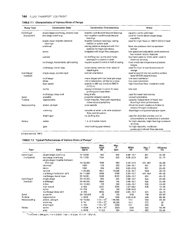
144  FLUID TRANSPORT  EQUIPMENT

                TABLE 7.1.  Characteristics of Various Kinds of Pumps
                  Pump Type         Construction Style        Construction Characteristics          Notes
                Centrifugal   single-stage overhung, process type   impeller cantilevered beyond bearings   capacity varies with head
                 (horizontal)   two-stage overhung        two impellers cantilevered beyond   used for heads above single-stage
                                                           bearings                      capability
                              single-stage impeller between   impeller between bearings; casing   used for high flows to 1083ft (330 m) head
                               bearings                    radially or axially split
                              chemical                    casting patterns designed with thin   have low pressure and temperature
                                                           sections for high-cost alloys   ratings
                              slurry                      designed with large flow passages   low speed and adjustable axial clearance;
                                                                                         has erosion control features
                              canned                      no stuffing box; pump and motor   low head capacity limits when used in
                                                           enclosed in a pressure shell   chemical services
                              multistage, horizontally split casing   nozzles located in bottom half of casing   have moderate temperature-pressure
                                                                                         ranges
                              multistage, barrel type     outer casing contains inner stack of   used for high temperature-pressure
                                                           diaphragms                    ratings
                Centrifugal   single-stage, process type   vertical orientation         used to exploit low net positive section
                 (vertical)                                                              head (NPSH) requirements
                              multistage                  many stages with low head per stage   low-cost installation
                              inline                      inline installation, similar to a valve   low-cost installation
                              high speed                  speeds to 380 rps, heads to 5800 ft   high head/low flow;  moderate costs
                                                           (1770 m)
                              slump                       casing immersed in sump for easy   low cost
                                                           priming and installation
                              multistage, deep well       long shafts                   used for water well service
                Axial         propeller                   propeller-shaped impeller     vertical orientation
                Turbine       regenerative                fluted impeller. Flow path resembles   capacity independent of head;  low
                                                           screw around periphery        flow/high head performance
                Reciprocating   piston, plunger           slow speeds                   driven by steam engine cylinders or
                                                                                         motors through crankcases
                              metering                    consists of small units with precision   diaphragm and packed plunger types
                                                           flow control system
                              diaphragm                   no stuffing box               used for chemical slurries; can be
                                                                                         pneumatically or hydraulically actuated
                Rotary        screw                       1, 2, or 3 screw rotors       for high-viscosity, high-flow high-pressure
                                                                                         services
                              gear                        intermeshing gear wheels      for high-viscosity, moderate-
                                                                                         Dressurehnoderate-flow services
               (Cheremisinoff, 1981).
                TABLE 7.2. Typical Performances of Various Kinds of Pumpsa

                                                                    Max       Max
                                                       Capacity     Head       P       NPSH       Max T    Efficiency
                    Type               Style            (gpm)        (ft)     (psi)     (ft)       ("F)      (%I
                Centrifugal   single-stage overhung    15-5,000      492       600    6.56-19.7    851      20-80
                 (horizontal)   two-stage overhung     15-1,200     1394       600    6.56-22.0    851      20-75
                              single-stage impeller between
                               bearings                15-40,000    1099       980    6.56-24.9   401-851   30-90
                              chemical                   1000        239       200    3.94-19.7    401      20-75
                              slurry                     1000        394       600    4.92-24.9    851      20-80
                              canned                    I-20,000    492  1   10,000   6.56-19.7   1004      20-70
                              multistage horizontal split   20-1 1,000   5495   3000   6.56-19.7   40 1-500   65-90
                              multistage,  barrel type   20-9,000   5495      6000    6.56-19.7    851      40-75
                Centrifugal   single stage             20-10,000     804       600    0.98-19.7    653      20-85
                 (vertical)   multistage               20-80,000    6004       700    0.98-19.7    500      25-90
                              inline                   20-12,000     705       500    6.56-19.7    500      20-80
                              high speed                5-400       5807      2000    7.87-39.4    500      10-50
                              sump                     10-700        197       200    0.98-22.0             45-75
                              multistage deep well      5-400       6004      2000    0.98-19.7    40  1    30-75
                Axial         propeller                20-100,000     39       150      6.56       149      65-85
                Turbine       regenerative              1-2000      2493      1500    6.56-8.20    248      55-85
                Reciprocating   piston, plunger        10-1  0,000   1.13  X IO6   >50,000   12.1   554     65-85
                              metering                  0-10      1.70~  io5   50,000   15.1       572        20
                              diaphragm                 4-100     1.13~ lo5   3500      12.1       500        20
                Rotary        screw                     1-2000    6.79 x lo4   3000     9.84       500      50-80
                              mar                       1-5000      11,155     500      9.84       653      50-80
                     ~
                   a 1 m3/min = 264 gpm,  1 m = 3.28 ft,  1 bar = 14.5 psi, "C = ("F - 32)/1.8.