
Page 173 - Chemical Process Equipment - Selection and Design
P. 173
7.5. EQUIPMENT FOR GAS TRANSPORT 145
TABLE 7.3. Operating Ranges of Some Commercial Vacuum Figure 7.7(c). To the left the developed head increases with flow,
Producing Equipment but to the right the head decreases with increasing flow rate. At the
peak the flow pulsates and the machine vibrates. This operating
Operating Range point is called the surge limit and is always identified by the
Type OB PIJNIP 6mm Hg)
manufacturer of the equipment, as shown on Figure 7.25 for those
Reciprocating pisi on centrifugal and axial machines. Stable operation exists anywhere
I-stage 760-1 0 right of the surge limit. Another kind of flow limitation occurs when
2-stage 760-1 the velocity of the gas somewhere in the compressor approaches
Rotary piston oil-sealed sonic velocity. The resulting shock waves restrict the flow; a slight
I-stage 760-10-’ increase in flow then causes a sharp decline in the developed
2-stage 760-10-3 pressure.
Centrifugal multistage (dry) liquid jet 760-200
Mercury Sprenisjel 760-10-3 Table 7.6 shows as many as 12 stages in a single case. These
Water aspirator (18°C) 760-15 machines are rated at either 10K or 12K ft/stage. The higher value
Two-lobe rotary blower (Roots type) 20-10-~ corresponds to about 850 ft/sec impeller tip speed which is near the
Turbomolecular 10-’-10-’0 limit for structural reasons. The limitation of head/stage depends on
Zeolite sorption [liquid nitrogen cooled) 760-1 0-3
Vapor jet pumps
Steam ejector
1-stage 360-100
&stage 360-1 0
3-stage 760-1
4-stage 760-3 x IO-’
5-stage 760-5 X 1 O-’
Oil ejector (I-stage) 2-10-2
Diffusion-ejecta r 2-10-~
Mercury diffusilm with trap
1-stage 10-’-<10-6
&stage I-<
3-stage lo-<
Oil diffusion
1-stage IO-’-5 x
&stage fractionating (untrappedf 5x 10-’-10-~
4-stage fractionating (trapped) 5x 10-’-10-’2
Getter-ion (sputter-ion) 10-~-10-”
Sublimation (titanium) 10-~-10-”
Cryapurnps 120 K) 1 0 -2- 1 0 -10
Cryosorption (15 K) 10-2-1 0-12
(Encyclopedia of Chemical Technology, Wiley-lnterscience, New
YO&, 1978-1 9841.
fans. Figure 7.24 allows exploration of the effects of changes
in specific speed or diameter on the efficiencies and other
characteristics of fans. The mutual effects of changes in flow rate,
pressure, speed, impeller: diameter, and density are related by the
“fan laws” of ’Table 7.5, which apply to all rotating propelling
equipment.
COMPRESSORS
The several kinds of commercial compressors are identified in this
classification:
1. Rotodynamic:
a. Centrifugal (radial flow)
t. Axial flow
2. Positive displacement 1 15 2 3 4 5 6 78910 15 20 30 40 50 70 90100
a. Reciprocating piston CAFACITY. 100 GPM
ba Rotary (screws, blades, lobes, etc.). (a)
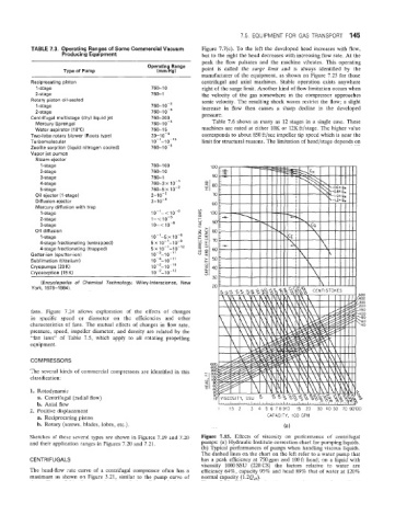
Sketches of thes,e several types are shown in Figures 7.19 and 7.20 Figure 7.15. Effects of viscosity on performance of centrifugal
and their application ranges in Figures 7.20 and 7.21. pumps: (a) Hydraulic Institute correction chart for pumping liquids.
(b) Typical performances of pumps when handling viscous liquids.
The dashed lines on the chart on the left refer to a water pump that
CENTRIFUGALS has a peak efficiency at 750gpm and 1OOft head; a liquid with
viscosity 1000 SSU (220 CS) the factors relative to water are
The head-flow irate curve of a centrifugal. compressor often has a efficiency 64%, capacity 95% and head 89% that of water at 120%
maximum as shown on Figure 3.21, similar to the pump curve of normal capacity (1.2QH).