
Page 177 - Chemical Process Equipment - Selection and Design
P. 177
7.5. EQUIPMENT FOR GAS TRANSPORT 149
Di
rd
ed
es
(e)
Figure 7.19.--(conlirzued)
Capacity. cubic ft per rnin Capacity. cubic ft per rnin
(a) (b)
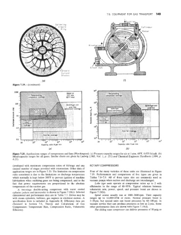
Figure 7.20. Applications ranges of compressors and fans (Worthington): (a) Pressure-capacity ranges for air at 1 atm, 60T, 0.075 lb/cuft. (b)
Head-capacity ranges for all gases. Similar charts are given by Ludwig (2983, VoE. 1, p. 251) and Chemical Engineers Handbook (2984, p.
6.21).
developed with maximum compression ratios of lO/stage and any ROTARY COMPRESSORS
desired number of stages provided with intercoolers. Other data of
application ranges are in Figure 7.20. The limitation on compression Four of the many varieties of these units are illustrated in Figure
ratio sometimes is due to the limitations on discharge temperature 7.19. Performances and comparisons of five types are given in
which normally is kept below 300°F to prevent ignition of machine Tables 7.8-7.9. All of these types also are commonly used as
lubrications when oxidizing gases are being compressed, and to the vacuum pumps when suction and discharge are interchanged.
fact that power requirements are proportional to the absolute Lobe type units operate at compression ratios up to 2 with
temperature of the suction gas. efficiencies in the range of SO-95%. Typical relations between
A two-stage double-acting compressor with water cooled volumetric rate, power, speed, and pressure boost are shown in
cylinder jackets and intercooler is shown in Figure 7.18(c). Selected Figure 7.19(b).
dimensional and performance data are in Table 7.7. Drives may be Spiral screws usually run at 1800-3600 rpm. Their capacity
with steam cylinders, turbines, gas engines or electrical motors. A ranges up to 12,000CFM or more. Normal pressure boost is
specification form is included in Appendix B. Efficiency data are 3-20psi, but special units can boost pressures by 60-1OOpsi. In
discussed in Section 7.6, Theory and Calculations of Gas vacuum service they can produce pressures as low as 2psia. Some
Compression: Temperature Rise, Compression Ratio, Volumetric other performance data are shown with Figure 7.19(d).
Efficiency. The sliding vane compressor can deliver pressures of 50 psig or