Page 179 - Chemical Process Equipment - Selection and Design
P. 179

. Performance Characteristics of Fans”
                     I
                                       Quantity                      Diameter
                                      (1000adm9   Head   Opt.          (in.)
                                                 Inches   V   Max                          Peak
                         Description   Min   Max   Water   (fps)   ad   Min   Max   Ns   0,   Eff.
                     Axial propeller   8     20   10     410   0.13   23   27   470   0.63   77
                     Axial propeller   20    90    8     360   0.12   27   72   500   0.60   80
                     Axial propeller    6   120    2.5   315   0.10   27   84   560   0.50   84
                     Raldial air foil   6   100   22     250   0.45   18   90   190   0.85   88
                     Radiai BC         3     35   18     260   0.63   18   90   100   1.35   78
                     Raldial open MH   2     27   18     275   0.55   18   66   97   1.45   56
                     Raldial MH        2     27   18     250   0.55   18   66   86   1.53   71
                     Radial IS         2     27   18     250   0.55   18   66   86   1.53   66
                     Vane 51 flat       1    10   12     250   0.43   10   30   210   0.81   70
                     Wane FC            1    10    2     65   1.15   10   30   166   0.65   66
                     I-
                        aqad = 32.2H/p,   N,  = IVQ~”/~”~ (specific  speed),  D,  = Db@’5/Qo.5   (specific  diameter),  where
                     D = diameter (ft),  H = head (ft),  0 =suction flow rate (cfs), V= impeller tip speed (fps), and N = rotation speed
                     (rpm).
                        (Evans, 1979).

                     I     I     I


                                                        14    TABLE 7.5.  Fan Lawsa
                                                                 Fan                        Variables
                                                                 Law
                             Head-Capacity at           12     Number  Ratio of   -   Ratio   X   Ratio   Ratio
                            \ 900  rprn
                                                                l  a   cf m       size’   X   rpm          1
            500                                                    b   press   -   size’   X   rprn‘   X   6
                                                                   C   HP         size5   X   rpm3         6
                                                                2  a   cfm        size’   X   press”*    1/6’/‘
                                                                   b   rpm    -  l/size   X   press”’   X   1/6’“
                                                                   C   HP         size‘   X   press”’    1/6’12
                                                                3  a   rp m       size'   X   cfm          ?
                                                                   b   press   -  l/size4   X   cfm2   X   6
                                                                   C   HP        l/size4   X   cfm3        6
                                                                4  a   cfm        sizew3   X   H P1I3
                                         *  BHP  at  900  rprn
                                                                   b   press   -  1/sizew3   X   H Pz3   X
                                                                   C   rpm       1 /sizeY3   X   HP’I3
                                                                5  a   size       cfm’/’   X   1/pressli4
                                                                   b   rpm    -  l/cfm”*   X   pressw4   X
                                                                   C   HP         cf  m   X   press
                                                       I
             0                                          0       6  a   size       cfm’I3   X   l/i-pm’13
              0    25    50     75    100   I2j    150             b   press   -   cfmz3   X   rPm;;   X
                            Capacity,  KCFM                        C   HP         cfmS3   X   rPm
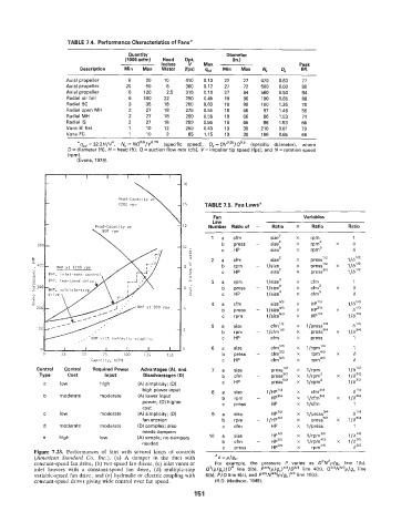
            Control   CointroU   Required Power   Advantages (A),  and   7  a  size   press”’   X   l/rpm
             3w      Cost       input       Disadvantages (D)      b   cfm    -   press”’   X   l/rpm’   X
              a    low         high       (A) simplicity; (D)      C   HP         pressY’   X   l/rpmz
                                            high power input    8  a   size      1/HPlf4   X   cfmZ4
              b    moderate    moderate   (A) lower input          b   rpm    -   H P3/4   X   1 /c~m514   X
                                           power; (D) higher       C   press      HP      X   l/cfm
                                           cost
              c    low         moderate   (A) simplicity;  (D)   9  a  size       HP”*    X   l/press3I4
                                           fan erosion             b   rpm    -  1/HP”’   X   pressY4   X
              d    moderate    moderate   (D) complex;  also       C   cfm        HP      X   l/press
                                           needs dampers
              e    high        low        (A) simple;  no dampers   10   a   size   HP1I5   X   l/rpmZ5
                                           needed                  b   cfrn   -   HPw5    X   l/rpmE   X
                                                                   C   press      HPa5    X   wm
           Figure  7.23.  Performances  of  fans  with  several kinds  of  controls
           (American  Standard  Co.  Znc.).  (a)  A  damper  in  the  duct  with   = 6 = P/gc
           constant-speed fan drive, (b) two-speed fan driver, (c) inlet vanes or   For  example,  the  pressure  P  varies  as  D2N’p/g,  line  l(b),
           inlet  louvers  with  a  constant-speed  fan  drive,  (d)  multiple-step   Qz(p/g,)/D4  line  3(b), ,Pz3(p/gc)1f3/Dw3 line  4(b),  Qa3Af4/’p/g,  line
           variable-speed fan drive, and (e) hydraulic or electric coupling with   6(b), PI0 line 8(c), and Pa5Nw5(p/gc)”5 line lO(c).
           constant-speed. driver giving wide control over fan speed.   (R.D. Madison, 1949).

                                                           151
   174   175   176   177   178   179   180   181   182   183   184