Page 183 - Chemical Process Equipment - Selection and Design
P. 183

7.6. THEORY  AND  CALCULATIONS  OF  GAS  COMPRESSION  155

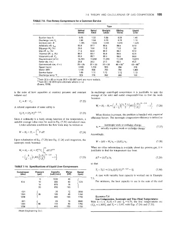
                       TABLE 7.9.  Five Rotary Compressors for a Common Service


                                                     Helical   Spiral   Straight   Sliding   Liquid
                                                      Screw   Axial    Lobes    Vanes      Liner
                           Suction loss 8,            9.35     1.32    0.89     0.90       1.40
                           Discharge ioss Oe          7.35     1.04    0.70     0.70       1.10
                           Intrinsic cow. B           1.185    1.023   1.016    1.016      1.025
                           Adiabatic eff. qad         85.6    97.7    98.5      98.5      97.9
                           Slippage W,  (%)           28.5    16.6    11.8      11.8       3.0
                           Slip e%. qs (%)           71.5     83.4    88.2      88.2      97.0
                           Thermal eff. qt (%)        89.2    93.7    95.8      95.5      42.5
                           Volumetric eff, E,,,       58.0    85.7    89.1      89.9      96.6
                           Displacement (cfrn)        14,700   1 1,550   1 1,220   11,120   10,370
                           Rotor dia. (in.)           26.6    25.2    27.0      65.0      45.5
                           Commercial size,  d x L   25x25    22x33   22x33    46~92~  43 x 4klb
                           Speed (rpm)                3,500   1,250    593       284       378
                           Motor (HP)                 1,700    800     750       750       1.400
                           Service factor             1.09     1.11    1.10     1.12       1.10
                           Discharge temp "F           309     270     262       263       120
                          "Twin 32.5 x 65 or triplet 26.5 x 33 (667 rpm) are more realistic.
                          bTwwin 32 X  32 (613 rpm) alternate where  L = d.
                          (Evans, 1979).

           is  the  ratio  of  heat  capacities at  constant  pressure  and  constant   In  multistage centrifugal compression it  is  justifiable  to  take  the
           volume and                                         average of  the  inlet  and  outlet  compressibilities so that  the work
                                                              becomes
              C"  =R - Cp.                             (7.22)
                                                                                                (k-1)lk
                                                                                   -
                                                                              __
           A related expression of  some utility is               Ws=H2-Hl= (kkl)(Z1~Z2)RTl[(~)  -I].     (7.26)
              TZ/T1 = (Pz/P1)(k-1)l'C.                 (7.23)
                                                                  When friction is present, the problem is handled with empirical
           Since k  ordinarily is a fairly strong  function of  the temperature,  a   efficiency factors. The isentropic compression efficiency is defined as
           suitable average value must be used in Eq. (7.20)  and related ones.
              Under adiabatic conditions the flow work may be written as   isentropic work or enthalpy change
                                                                                                          (7.27)
                          9                                       " = actually required work or enthalpy change '
              W = Sr, - Hl   V dP.                     (7.24)
                       =
                                                              Accordingly,
           Upon substitution of Eq. (7.20) into Eq. ('7.24)  and integration, the
           isentropic work becomes                                W = AH  = Ws/qs = (AH)s/qs.             (7.28)
                                                              When no other information is available about the process gas, it is
                                                              justifiable to find the temperature rise from

                                                       (7.25)

                                                              so that
           TABLE 7.10.  Specifications of Liquid Liner Compressors
                                                                 T2= Tl(l + (1/"/P1)'"~"'k-   1 I.        (7.30)
             Compressor   Pressure   Capacity   Motor   Speed
               (size)     (psi)    (cuft/rnin)   (HP)   (rpm)    A  case with variable heat  capacity is  worked out in  Example
                            5        1020      40             7.5.
                K-5        10         990      60                For  mixtures, the  heat  capacity to use is  the  sum of  the  mol
                           15         870     100  ('.
                                               75
                           20         650
                621                   26       7;     3500
               1251        35         120      40     1750
               1256                   440     100     1750       EXAMPLE 7.4
                                                                 Gas Compression, Isentropic and True Final Temperatures
                621                   23       10     3500    With  k = 1.4,  P2/Pl = 3  and  qs = 0.71;  the  final temperatures  are
               1251       k0          110      50     1750    (Tz)s = 1.369T1 and Tz = 1.519T1 with Eqs. (7.24) and (7.31).
               1256                   41 0    150     1750
              (Nash Enginleering Co.).
   178   179   180   181   182   183   184   185   186   187   188