
Page 178 - Chemical Process Equipment - Selection and Design
P. 178
150 FLUID TRANSPORT EQUIPMENT
0.1 0.3 0.6 1 3 6 10 30 60 100 300 6001ooo 3ooo 10,ooo
Specific speed, Ns
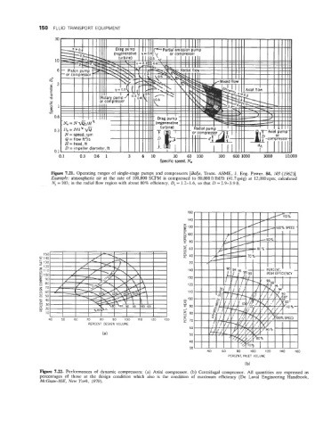
Figure 7.21. Operating ranges of single-stage pumps and compressors [Balje, Trans. ASME, J. Eng. Power. 84, 103 (1962)l.
Example: atmospheric air at the rate of 100,000 SCFM is compressed to 80,000 ft lbf/ft (41.7 psig) at 12,000 rpm; calculated
N, = 103; in the radial flow region with about 80% efficiency, D, = 1.2-1.6, so that D = 2.9-3.9 ft.
160
140
5 120
0
5 100
0 80
CK
I
I--
3 60
U
U
40
20
140
130
120
110
n 100
a
y 90
+-
E eo
a:
0 70
PERCENT DESIGN VOLUME
60
(a) 50
40
30
40 60 80 100 120 140 160
PERCENT, INLET VOLUME
(b)
Figure 7.22. Performances of dynamic compressors: (a) Axial compressor. (b) Centrifugal compressor. All quantities are expressed as
percentages of those at the design condition which also is the condition of maximum efficiency (De Lava1 Engineering Handbook,
McGxaw-Hill, New York, 1970).