
Page 288 - Chemical Process Equipment - Selection and Design
P. 288
9.8. PNEUMATIC CONVEYING DRYERS 255
(6) (d)
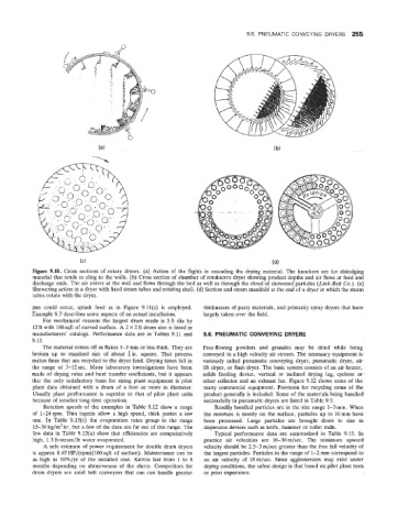
re 9.10. Cross sections of rotary dryers. (a) Action of the flights in cascading the drying material. The knockers are for dislodging
material that teinds to cling to the walls. (b) Cross section of chamber of rotolouvre dryer showing product depths and air flows at feed and
discharge ends. The air enters at the wall and flows through the bed as well as through the cloud of showered particles (Link-Belt Co.). (c)
Showering action in a dryer with fixed steam tubes and rotating shell. (d) Section and steam manifold at the end of a dryer in which the steam
tubes rotate with the dryer.
pan could occur, splash feed as in Figure 9.11(c) is employed. thicknesses of pasty materials, and primarily spray dryers that have
Example 9.7 describes some aspects of an actual installation. largely taken over the field.
For mechanical reasons the largest drum made is 5ft dia by
12 ft with 188 sqft of curved surface. A 2 x 2 ft drum also is listed in
manufacturers' catalogs. Performance data are in Tables 9.11 and 9.8. PNEUMATIC CONVEYING DRYERS
9.12.
The material comes off as flakes 1-3 nim or less thick. They are Free-flowing powders and granules may be dried while being
broken up to standard size of about $in. square. That process conveyed in a high velocity air stream. The necessary equipment is
makes fines that are recycled to the dryer feed. Drying times fall in variously called pneumatic conveying dryer, pneumatic dryer, air
the range of 3-12 sec. Many laboratory investigations have been lift dryer, or flash dryer. The basic system consists of an air heater,
made of drying rates and heat transfer coefficients, but it appears solids feeding device, vertical or inclined drying leg, cyclone or
that the only satisfactory basis for sizing plant equipment is pilot other collector and an exhaust fan. Figure 9.12 shows some of the
plant data obtained with a drum of a foot or more in diameter. many commercial equipment. Provision for recycling some of the
Usually plant performance is superior to that of pilot plant units product generally is included. Some of the materials being handled
because of steadier long time operation. successfully in pneumatic dryers are listed in Table 9.5.
Rotation speeds of the examples in 'Table 9.12 show a range Readily handled particles are in the size range 1-3 mm. When
of 1-24rpm. Thin liquids allow a high speed, thick pastes a low the moisture is mostly on the surface, particles up to 10mm have
one. In Table 9.13(c) the evaporation rates group in the range been processed. Large particles are brought down to size in
15-30 kg/m2 hr but a few of the data are far out of this range. The dispersion devices such as knife, hammer or roller mills.
few data in Table 9.13(a6) show that efficiencies are comparatively Typical performance data are summarized in Table 9.13. In
high, 1.3 Ib steam/lb water evaporated. practice air velocities are 10-30 m/sec. The minimum upward
A safe estimate of power requirement for double drum dryers velocity should be 2.5-3 m/sec greater than the free fall velocity of
ns approx 0.67 11P/(rpm)(100 sqft of surface). Maintenance can be the largest particles. Particles in the range of 1-2 mm correspond to
as high as 10%/yr of the installed cost. Knives last from 1 to 6 an air velocity of 25m/sec. Since agglomerates may exist under
months depending on abrasiveness of the slurry. Competitors for drying conditions, the safest design is that based on pilot plant tests
drum dryers are solid belt conveyors that can can handle greater or prior experience.